Sunday, July 7, 2019

The End of the Line

Today's Denver Union Station.
Okay, perhaps a little dramatic, but there are a few truly dramatic and iconic scenes I want on the layout. Denver’s Union Station is one of them. From the downtown side of the station, only a little has changed with the recent renovation, but the same is not true on the railroad side of the station. Fortunately, this all came to pass after my intended modeling era. So, I can still capture the old station that I remember from my childhood. But there is something iconic in my mind about this structure and so I must have it on the layout. And, I want to have it in something close to scale size. There are only a couple of structures that I want to represent with such fidelity on my layout, and this is one of them.

Denver Union Station from above in full-size N-scale.
At more than 13-inches wide, almost 40-inches long and a little more than 6-inches tall, it will be an impressive and challenging model to build that will dominate the scene. It will also be one of the first things visitors will see when they come to the layout, so I think it is worth the space. One advantage of the renovation project is that a lot of information and drawings of the station became available as a part of the architectural reviews. There is even at least one good book on the station that was authored by Rhoda Beck, who is affiliated with the renovation project as well as another classic book on the Railroads of Denver.

The depot dates to 1881 but has been rebuilt several times. As such, different portions of the structure embody different architectural aesthetics. Fortunately, the 2014 renovation project that rebuilt and revitalized the station led to a great deal of information about the station both before and after that is available on-line. I’ve been collecting this information and using it to build a set of drawings to use to create the station. The diagram above is the result of the need to produce an overhead view to include in the planning process. 

There are some compromises that I have accepted in the planning of the model. Based on the location of Prospect Junction and the aisle-way, the station should be in the background, behind the tracks. Given my space though, that would make it unnecessary to build more than a flat model of the station. With the anticipated effort of this model, I want it up front. So, it is going to be on the wrong side of the tracks based on everything else. This also means that trains are coming into the station from the left as you view the front of the station, where it would be correct for them to be coming in from the right. So, there is a compromise here that allows me to put the station up front. 

Configuration of the Denver Union Station Layout Design Element.
Similarly, this means that the modeled tracks are numbered in reverse. I have decided to standardize my track numbers from the aisle side to the rear across the layout to make it easier for operators. This does put Track 1 closest to the station, but means I have to rearrange the throat of the station as well. I ultimately decided that I would model 7 tracks at the station. I believe that the station had only 6 at the time I am modeling, although it now has 8 dedicated to heavy rail operations. I do have a plan from the National Archives where there are 13 tracks shown, so the number has fluctuated over the years. Ultimately though, I made my decision based on operational considerations. In this era, Denver saw as many as six Amtrak trains per day, including the California Zephyr, the Pioneer and the Desert Wind. Technically, the Desert Wind was combined with the California Zephyr through Denver (dividing at Ogden/Salt Lake City) to head to Las Vegas. Similarly, during part of this time period, the Pioneer was combined at Denver before continuing to Chicago, although for a period, the Pioneer also was combined until Salt Lake where it would head northwest to Portland. There also was a period of time where the Pioneer traveled separately via Cheyenne over UP’s Overland Route. Anyways, depending on how I want to model it, I may have as many as three Amtrak trains in the station at once. Furthermore, there were times during this period where the California Zephyr was as much as 16 Superliner Cars pulled by 4 engines (possibly with Material Handling Cars too). This massive train would be more than 10 feet long. 

In addition to these trains, I plan to include a provision for the DRGW Ski Train, a train such as the UP Frontier Days Train (which could take up 2 tracks), a freelanced additional train (maybe a Hollywood Special or a Steamboat Skier that would use vintage California Zephyr cars), and an additional track for some possible commuter rail. It is a little early for commuter rail in the area, as that is just now taking off, but there were some discussions in the late 1990s about a service between Denver and Albuquerque, as well as simply Denver to Colorado Springs/Pueblo. Most of these additional trains would not add much action to the mainline, but since I love passenger trains and have collected several of them, I have decided that I would like to be able to model them in some fashion on the layout if I choose to do so. The seven tracks range from 116-inches to 149-inches, so all of the tracks are suitably long to represent substantial passenger trains that complement the model of the station.

All of the turnouts are designed as #10 turnouts to further complement the passenger traffic, and while the throat is not an exact model of the one used in Denver, it is functionally similar. At various eras, the station also had a couple of spurs that served local industries, so I have decided to include these as well. I do not believe any were in use in the era I am modeling, but a couple of plausible extra spurs never hurts operations.

Most of this part of the layout can be built on a 16-inch deep shelf hung off the wall. That should make it fairly easy to build this part in sections, and even relocate it if necessary. However, there is one complication. As can be seen in the upper right-hand corner, to fit this in, I did have to extend the station in front of the access to the crawlspace and build this section of the layout to a depth of 32-inches. I have decided to build this end of the Layout Design Element (LDE) as its own removable module. I will probably even mount it on wheels so that it can be disconnected and rolled out of the way to provide access to the crawlspace when needed. Given that access to the crawlspace is a rare necessity, I think that this is an acceptable compromise of my standards. This module can even be removed from the room and taken for display at train shows if necessary. The depth of the module does pose a bit of an access problem for the tracks in the rear but given that these are all straight tracks without turnouts or other complicating features, I think that the derailment risk and maintenance issues are manageable.

BNSF Rennick Yard in Denver February 23, 2013 by Mike Danneman.

So, there it is, Denver Union Station fits into the area of the layout just as I had hoped it would. With this sketched into the plan, the next step is to develop the plan on the other side of the aisle through the BN Rennick Yard and onto the DRGW North Yard.


Cameron Turner


Thursday, July 4, 2019

Adding a Twist…

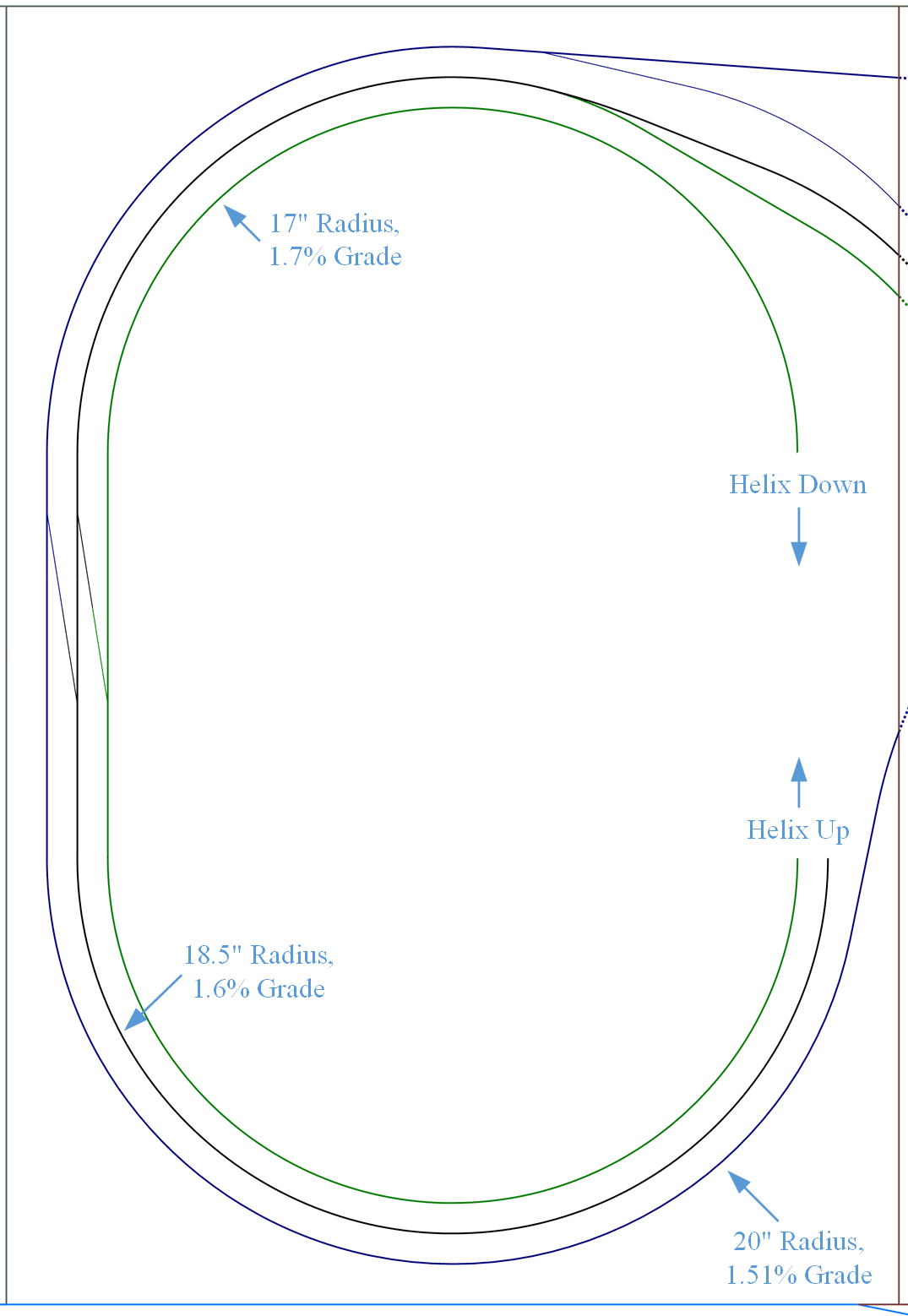
The helix is a critical element to the plan for the layout, so its design was one of the driving factors in the configuration of the layout. The purpose of the helix is two-fold. First, it is intended to connect the various “exits” from the modeled layout to the various staging yards. Second, because I desire to make the layout as close to self-staging as possible (so as to minimize the effort required between operation sessions), the helix provides a continuous loop option between the ends of the layout. Because of the grade of the layout and its multiple deck nature, this means that the helix could become quite a bottleneck, which has led me to double track the helix for most of its length.

Helix Diagram.

And its length will likely be substantial. Exiting the layout near Prospect Junction, I am predicting that the upper entrance of the layout (modeling somewhere west of Tabernash, Colorado if all goes well) will be around 37.5-inches above Prospect Junction. With a target climb per lap of the helix of 2.5-inches, this means that there will be about 15 laps in the helix. That is a lot of track, and it will need to be pretty much bullet proof.

So, where do these numbers come from? Well, let’s take a look at how I came up with 2.5” for a lap of the helix. I plan on laminating the helix sub-roadbed together using two layers of 1/8-inch wood with any joints staggered. This gives me a 1/4-inch thickness. Add to that an 1/8-inch thick cork roadbed, and another 1/8-inch thickness for the track and that gets me to a total of ½-inch thickness. NMRA Recommended Practices suggest that a in N-scale, 1 23/32-inch is necessary over the railheads. I round this up to 2-inches to give me a little wiggle room. And there we go, 2.5-inches. This also similar to the MRVPCanadian Canyons layout railhead-railhead height in their helix. I’ve previously commented on that layout and its inspirations to my own efforts. It is well worth the cost of an MRVP subscription to watch this excellent series.

Model Railroaders Canadian Canyons Layout showing their completed helix.
My design has as many as 3 loops of track in the helix. The loops will have 1.5-inch spacing, consistent with Ntrak standards, and more generous than I am going to use in the rest of the layout. The inner loop will have a 17-inch minimum radius, the middle loop will have a 18.5-inch minimum radius, and the outer loop will have a 20-inch minimum radius. Unfortunately, the purpose of the outer loop is often for activities other than climbing the helix, but I’ll explain more in a future helix design post. However, radius is a major concern. Fortunately, I do have some data to work with here. MRVP used a helix with 16.5-inch and 18.5-inch radius curves and a lap-over-lap rise of 2 3/16-inches. (David Popp says it is only 2-inches in the videos on the layout, but he left out the thickness of the subroadbed in his calculations.) This results in a grade of 2.1% on the 16.5-inch radius inner loop and 1.9% on the 18.5-inch outer loop. MR regularly runs trains of 18-22 cars with 2 engines up these grades without issue.

Layout Main Helix Design
This compares well with my design. I have 17-inch to 20-inch radius curves, so my performance should be in the same ballpark as that of Canadian Canyons. However, because my helix is an oval instead of a circle, I get two benefits. First of all, in order for a train to have cars on the entirety of both curved ends of the helix, it would need to have at least 35 50’ cars, and then only 30 of the cars would be on the curved sections. Part of my grade is handled with straight sections which will have less rolling resistance. Second, because my helix is an oval, I get a larger lap to gain elevation due to the two 20-inch straight sections. The result is that my helix has grades of 1.7% (inner loop), 1.6% (middle loop) and 1.51% (outer loop). Thus, I should exceed the performance of the trains that is achieved in the Canadian Canyons loop with the same clearances and a slightly more substantial (by 1/16-inch) subroadbed.


Based on some experimentation, I’ve targeted a “long” unit coal train of approximately 36 cars with the possibility of a caboose and 3 engines in the helix. On the layout, the train would generally run with 2 additional swing helper engines per DRGW practices. I want to do some testing of my own, but I expect that I will be able to achieve these train lengths using this number of locomotives based on the Canadian Canyons layout. One last point, most of the time, I plan to use the inner loop as the downward loop, and the middle or outer loop as the upward loop, which will further minimize the grades. Indeed, it is on the visible layout where grades of 2%+ will be faced by the trains on the mainline where the ruling grades will lie.

One last note: A Happy Fourth of July to everyone reading this blog and to those who have not yet found it. Take some time out to celebrate this country. Remember, this is a celebration of a common dream, not of any one person, place or thing. It is instead about America’s story, about our collective story as a nation, and that belief that has allowed people to make sacrifices to provide others with a chance to experience this dream. No one person is bigger than that story. That is why the story lives on and on and on. Live the story. Pursue the dream. Share the dream with those who are most in need of a dream. It is how the dream lives in each of us. Never surrender your dreams.

Cameron Turner


Wednesday, July 3, 2019

Wordless (almost) Wednesday...

The Iconic Sign on Denver's Union Station.
I've seen this feature on other blogs and enjoy it, so I am going to start trying to post a favorite image each Wednesday. So, here is the debut image in the series.

Cameron Turner

Tuesday, July 2, 2019

A Junction and a Helix

In the last post, I described my space and provided a conceptual benchwork configuration for my proposed layout. This post begins the description of the track plan for that layout. I often start my designs with a critical component. In this case, the component that I was most concerned about was the helix and how it would interface with the layout at Prospect Junction.

Prospect Junction in Denver Colorado - by James Belmont.
Prospect Junction in real life is an important connection. It is a double track diamond of the line into Denver Union Station from the DRGW's North Yard, and provides a connection to the BNSF and UP lines towards Wyoming and Nebraska used by Amtrak. DRGW and BNSF trains headed south for the Joint Line and Pueblo also pass by Prospect Junction. After leaving Denver Union Station, Prospect Junction is the first notable element on the ride west out of Denver.

The critical elements of the junction in my mind are as follows:

  • The double diamonds crossing the BNSF main to the Joint Line;
  • The bridge over the South Platte River;
  • The connection to the BNSF wye for turning and cleaning passenger trains at Denver Union Station;
  • Connections to the DRGW line west, the BNSF and the UP lines headed north and east;
  • Proximity to the Joint Line traffic headed south; and
  • Proximity to the BNSF engine facility.

Unfortunately, the geometry of the junction is not particularly conducive to modeling as can be seen in this aerial view.
Aerial View of Prospect Junction.

My benchwork plan allocated a rectangular area for a helix. The helix supports up to three tracks on 1.5-inch (Ntrak mainline) spacing. This is a greater spacing than I think is necessary, but it provides a little extra spacing in a critical location. The inner loop of the helix does have a 17-inch radius. However, this track is intended for downhill running and I expect that it will be acceptable. Mike Danneman's layout has an 18-inch minimum radius and performs perfectly well. Even at this radius, the grade in the helix is 1.7%. This is only slightly more demanding than the standards used by Ntrak on their Blue Line.
Track Plan for Prospect Junction and the Helix.
I was able to capture the most important elements of the junction, including the double diamonds, the joint line traffic, the ability to turn a passenger train, and the connections at the station. (The bridge over the South Platte River has not yet been added to the drawing.) Trains from the west come into the station using the routing illustrated below.

Routing for Trains arriving from the West (DRGW).
So, trains arriving from the west via the DRGW will actually cross the diamond first on the double track mainline (not prototypical) but then loop around the helix and cross the diamond in the prototypical fashion (one a single track crossing a double track) before entering the station throat. To then reverse the consist, the train would back out of the throat headed towards the BNSF/UP yards (just as in the prototype) but rather than coming around a wye as in the prototype, the train simply runs around the helix and back through the junction and into the throat. Effectively, the loop is a reverse loop which is actually going to be less problematic than a wye for the same operation.

Reversing a Passenger Consist.
Furthermore, trains arriving or departing via the BNSF or UP lines that lead north east out of Denver (via the 31st Street and 38th Street Yards) can also enter and exit the station throat as shown below. These trains head in and out of the staging yards located above via the helix.

Passenger Train Connections to Staging.
The plan for Prospect Junction is not perfect (or perfectly prototypical) but it will function effectively both operationally and in terms of faithfully telling the story of a train leaving the station to travel Thru the Rockies...Not Around Them.

Cameron Turner
Sunday, June 30, 2019

The space that is the place...

I have previously described the space I have for my eventual layout in a prior post. I'll try not to repeat that post too much here. The space is pretty much as I described it in that post, with two rooms connected by a common wall. The initial space available is about 11' by 27'. Currently, there are three closets along one of the long walls and bookshelves along the other. In addition, there is a sink on the long wall next to the closets. Within one closet is a crawlspace access, which needs to be maintained. However, the closets and sink can be removed from the space (eventually).

Layout Space
On the other side of the bookcase is a family room which can double as a crew lounge. However, the bookcase needs to be retained as is. I am not opposed to that at all, as it provides a lot of space for my train books.

The second room is the garage. It is a four car, double tandem garage, about 38' deep and 24.5' wide. There are four support posts running down the center of the garage. The left wall has the electrical panels for the house on it, and three windows. A sump pump is located in the upper left-hand corner of the garage. The water heater is currently in the center of the garage, along with a workbench (not shown). The water heater can be moved, and the workbench is not needed. On the right wall, along the shared wall between the spaces is a sink and a second washing machine. Also on that wall, but below the door to the initial layout space is the radon venting system. 

Right now, the garage is to be home for my wife's boat and her classic car. The footprints for these items are shown. Right now, the rest of the garage is being used for storage, but that will not need to be the case forever. In theory, that half of the garage is also layout space - although the boat also requires some space for the workshop to maintain and refurbish the boat. Right now, that space simply does not exist. 

The garage faces the rear of our house, with the driveway wrapping around the side of the house to climb a hill to the street. Below the driveway, there is another 9' or so of flat ground before we have a retaining wall that separates the back yard into an upper and lower area. The lower area leads to the Corps of Engineers line, and beyond that, the lake. 

Because we lack the space in the garage for the boat, its trailer, the classic car, the shop area necessary to support the boat, let alone storage yard tools or either of the cars my wife and I regularly use. Because of the configuration of our garage and driveway, the boat actually has to be manually rolled out of the garage and brought to the side of the house. In fact, even backing cars in and out of the garage is a little tricky with the nature of the driveway. 


So, my wife and I have been discussing an eventual idea to build a new garage off the old one. This new garage would extend into the driveway and provide three new stalls for cars/boats. This design would change the garage to a side loading configuration, which I believe will be no more difficult to pull cars in and out of and will likely be easier. The idea is shown below.

Possible "New" Garage
This concept converts the entire current garage to a layout area and a workshop area. The new garage would provide storage space, and space for the boat, the classic car and at least one of our other cars. The extension is not imminent, but it is possible someday. Even if this is not quite the concept that we go with, it seems conceivable that eventually half the garage will become available for a layout. So, I started exploring possible configurations for that space. 

Initial Garage Configuration
In the above configuration, I tried to maximize the amount of the existing garage retained for non-layout purposes. The dividing wall in the garage needs to avoid both the door to the rest of the house and the window on the opposite side of the room. This turns out to require some sort of offset in the wall to make this work. However, with this configuration, the layout side of the garage becomes approximately 22' by 24.5' or about 539 square ft. Combined with the space in the initial layout area (297 square feet) the total layout space becomes approximately 836 square feet. Throughout my arm chair planning, I have consistently desired approximately 800-1200 square feet for the layout (plus a lounge, dispatcher and shop space), so this total is on the low end of what I have always envisioned.


Working with this space, I developed a preliminary benchwork configuration, and sketched out the lowest level of the layout representing Denver Union Station to the Big 10 Curves. 

Initial Layout Benchwork Plan

From here, the layout would reverse itself at the Big 10 curves and retrace its path on a higher deck, ultimately wrapping around the room to connect to a third deck. Lapping around the room again, that third deck would re-enter the initial layout space above North Yard before plunging into the helix and staging. This gives me a layout with one nod under. The nod under would need to be removable, and there would need to be another removable section to provide garage access. Not ideal, but perhaps feasible. 

Because the shared wall between the space is full of plumbing for most of its width, I finally resolved to simply run the layout through the existing doorway. This unfortunately does result in a pinch point for those following their trains, but it and the nod under are each only faced twice during the run of a train, so I think this too is feasible. 

So, I have a concept for the layout and a benchwork configuration for the space. What about the layout? Next time, I will start describing the development of the track plan for this configuration and walk you through the considerations and changes I made as I developed the plan.

Cameron Turner

Sunday, June 23, 2019

Finding a Focus

 Finding a Focus

I started this blog by discussing a number of possible layout themes that I have been considering. These included:

  1. D&RGW Moffat Line (Denver to the Moffat Tunnel and Beyond)
  2. D&RGW Craig Branch (Bond to Craig)
  3. D&RGW Tennessee Pass (Pueblo to Minturn/Dotsero)
  4. D&RGW Soldier Summit
  5. D&RGW Belt Line
  6. Freelance "D&RGW-like" Line combining elements of the above
  7. D&RGW Marshall Pass Line (Nn3)
  8. RGS/D&RGW in Nn3 (Durango-Ridgeway/Silverton)
  9. Freelance Rio Gorre Northern in Nn3 (based on Colorado and Western NG lines)
  10. Colorado Central in Nn3 (Denver through Golden to Silver Plume/Central City)
  11. Wildcards...

Each of these I described in a separate blog post describing the line. And over the years I have started plans for almost all these lines. Yet, there are two I keep coming back to, and have probably done the most planning for over the years. These are the Moffat Line, and the Rio Gore Northern. These are basically two different lines, but I have pretty much concluded that right now, these are what I want to build. Furthermore, I am convinced that I want to focus on the Moffat Line as my primary operating layout. Does that mean I won’t but the Rio Gore Northern? No, I may well build it, but I think I will keep it smaller, and maybe use it as an interim layout that could be fully operational while the pieces come into place for the Moffat layout. After all, there are some things I would like to build and model that simply are not found on the Moffat line.

Three in a Row by Mike Danneman.
So, the main layout will be a Moffat Line focus. I chose this over Tennessee Pass, Soldier Summit and the Craig Branch primarily because it is close to my childhood home, and there is a nice mix of local switching, mainline operations and helper operations in the area. Tennessee Pass is a lot more limited for local switching traffic and Soldier Summit has even less. The Craig Branch is effectively Coal first, second and third, although there is a little switching along the way. Both Tennessee Pass and Soldier Summit really need to have either Pueblo or Provo included to provide any significant switching action and both of those terminals are a long distance away from the signature climbs. The Moffat is also a single-track railroad, so dispatching is more interesting than that of Soldier Summit. I want some local switching, an interesting dispatching layout and so the Moffat seems to be not only a nostalgic choice, but a good choice.

Mike Danneman Models the Yampa Valley Mail exiting the Moffat Tunnel.
Mike Danneman’s Moffat Line model however, demonstrates that the stretch of Denver to the East Portal of the Moffat Tunnel can be well modeled in a reasonable area. And given that I am more interested in a multi-deck layout than he was, suggests that I may be able to model this line in such a way as to produce a suitable operating layout with significant scenic potential. Finally, there are several nice elements to model, including Union Station, the Rio Grande Yard Tower, the Cargill Elevator, and the Moffat Tunnel itself. Each of these should be nice modeling projects.

I continue to follow Mike through his Flickr account (Flicker Handle Moffat Road). I still devour his articles in N Scale Railroading starting with (Issue #5 May/June 2001). I even got to visit the layout once and it does look fantastic. I still love watching the videos, like these below. I don’t want to duplicate his layout, but it certainly sets a standard. And I still watch and re-watch videos of his layout in action, like those at these links.

Mike Danneman's Moffat Line Slide Show.
Mike Danneman's Layout Video.
Mike Danneman's Layout Video Part 2.
So, with a slightly ambitious and audacious goal of building my own version of the Moffat Line, next time, we can delve into the space I imagine for the layout.

Cameron Turner


Saturday, June 22, 2019

Three months ago – I could have died…


It has been a while, more than three months actually since the last and in fact the only post so far in 2019. And so, there is a little bit of a need for a reboot on this blog, something I was thinking about as early as last spring, before things happened.

My last post was about the T-scale (1:450) layout I have been slowly building for the Central Model Railway and Historical Society Club and its second public show. About the time of the last post, I was planning how to get it ready for its third show last April. I missed the warning signals for a derail.

I had been seeing a doctor for being tired – nothing unusual there for those who know me. It is not like I have been known to not only burn the candle at both ends, but to also light it in the middle for good measure. But even for me I was tired. Four months of testing had suggested that I had some significant allergies. But we ran one more test. And that one came up with a result that sent me to a specialist. The specialist suggested another more definitive test, indicating that this was likely a false positive, maybe something relatively minor, but admitting that it could be more serious. So, a couple of weeks later, we ran the next test in the hospital.

It was supposed to take about an hour, and my wife settled down to wait for the results. Fifteen minutes later, the doctor was out, and simply said, “He needs surgery and we want a particular team of doctors to do the surgery, but they cannot do it until next Friday, so we are keeping him overnight to see if he can wait that long.”

A week later, I was checked into the hospital for open heart surgery. I hadn’t had a heart attack, but I was on my way to one, and it would have been a big one. The surgery led to a triple bypass, from which I have been recovering for the last three months.

While recovering, I have had a lot of time to think and to look at my priorities. I love model railroading, but it has always been something that has been something that I would immerse myself in later in my life. After this experience, I no longer am willing to wait for the perfect space, for the rest of my life to fall into place, or to let current uncertainties prevent me from enjoying my hobby. I want to do more than the limited things I have done for other clubs or projects. I want to build parts of my own railroad empire, even if those visions may not come to fruition as planned. Finally, I also recognize that model railroading is a major stress reliever for me, and that I need to prioritize that more in my life going forward as I recover from surgery.

So, what does this mean for the blog? Well, I hope that it means a new life for it. I plan on revamping it a bit. I am going to shift some of the posts on the T-layout to a separate blog for the club, and I am going to continue that layout. I am going to continue a number of the projects I started last year and to pursue my Master Model Railroader certificate with the NMRA. But I am also going to try to publish more regularly on this blog, and in other venues about my planned railroad. Three months of recovery has given me some time to think about and plan a layout. So, that is where I will begin the story, with the development of the plan. 

I don’t know if it is what I will build, or when it might be complete. But I have decided that there are plenty of tasks I can start doing to build parts of it. And rather than waiting to know that the final product can be built as I plan on building it, I am going to simply imagine the final product, and build while I await the other parts necessary for the layout to fall into place. In the meantime, I will enjoy the journey. So, all aboard for the journey. We are going Thru the Rockies…Not Around Them In 1:160.

All Aboard!

Cameron Turner

Tuesday, February 19, 2019

T Layout 2019

Well it has been a year since I first displayed a T-scale Layout for the Central Model Railway and Historical Society Club at the train show in Easley. And it is time again for the layout. While I did a few things since last year, I have to admit that I got a lot less done on the layout than I had planned last year. 

I did complete a few projects
  1. Details on the stone arch bridge
  2. Design, Print, Paint the brick pedestrian bridge
  3. Plan the roadways
  4. Install a few trees

But I was pretty disappointed to see how little I completed. Nonetheless, the layout performed well and I put together a few videos of a train on the layout...


The stone arch bridge is now just about ready for permanent installation. I've added the iron details and the drain pipes. I do need to trim the drain pipes back to ground level in a few spots, but that is a going to be a quick task.


I also added a few trees to the layout - wire armature trees near the water and a pine tree near the barn. I also added a small dog house near the barn...


After the weekend, I am pretty happy with the road layout, so one of the next projects will be to build and install the finished roads using vinyl graphics. Once the road is installed, I feel good about installing the bridges. 

The newest bridge looks really good - but it still needs to be permanently installed in the layout. 

New Pedestrian Bridge on the Left Hand Side of the picture.
The pedestrian bridge still needs to be cut into the scenery but the mirror will be very effective with the roadway running into it. 

The layout continued to remind me that the radii are a little tight for some of the longer equipment but short trains look best anyways. I have decided to add one more small bridge to the layout, located between the station and the tunnel to carry the railroad over a stream/river.

Scenery needs to be the focus going forward. The only construction still remaining is a bit of improvement to the lighting and backdrop. But those items will come after the scenery is substantially complete. I also was looking forward to testing my new PWM controller I got for the layout - unfortunately, I learned that the PWM controller actually takes AAA batteries - even though the box says AA - so that will be a later test. 


Tuesday, October 16, 2018

Designing a Layout - Determining the Footprint


With a subject identified, my next step is to consider the footprint available for the layout. That footprint is related to the desired architecture of the layout. In this case, I have selected that as well. In my earlier plan, I began to play with a concept I call a double helix layout, which is two nested helices, one climbing up and the other climbing back down. One or both could in theory be sceniced, but it allows the layout to climb to a summit and then descend the other side. For this layout, I plan on scenicing one helix, while hiding the other one, in large part due to the available space for the layout.


The room available for the layout is 11' wide, and 27'-9.5" long. The lower side of the room (in the drawing above is a built in bookcase that separates the room from an adjacent family room/crew lounge, which is not available for the layout. The upper wall is currently occupied by a set of 3 double door closets, and a built in sink. Within the upper right hand closet is an entrance to a crawl space which has to be maintained. The right wall also has the intake for the basement AC/heating system. The left wall has a door which exits into the garage.  Located on the opposite side of the wall in the garage is a utility sink and a washing machine, so that left wall is full of plumbing.

The closets and sink can be relocated - however, the closets represent a significant amount of storage for the house. However, at 32" deep, they could be reduced in depth if not eliminated. Similarly, the sink could be relocated, and consolidated with the sink in the garage - which I would also like to get out of the garage, along with the washing machine (if it cannot be eliminated altogether as it is not the primary washer in the house). Since the left wall contains plumbing, it makes sense to locate these elements on the left wall. Doing this, and replacing the closets with 16" depth shelves, results in the room plan below.


I've also extended the shelves over the new sink and washing machine. Allocating between 30" and 36" for aisles around the layout produces a possible footprint that is about 20'-9" long and between 44" and 56" wide.

My next concern is to determine how the hidden helix will affect the necessary width of the layout. Because the down helix will be a substantial run and will need to handle bidirectional traffic, it will need to be double tracked. In addition, there will need to be a third track in the helix, at least from the lowest staging level to the bottom of the visible portion of the layout. So, the helix is at least three tracks wide. Since two tracks have to run from the top of the helix to the bottom, those two will need to be the innermost tracks. Based on the Model Railroader Canadian Canyons layout, which used an N-scale Helix with a radii of 16.5" and 18.5", I plan to use an inner radius of 17" and to make this track the default downhill track. Based on my experience in Ntrak, I plan to use 1.5" track spacing in the helix, thus, this makes the radii of the helix 17" - 18.5" - 20". I'll add 2" to the inside and outside openings in the helix, so the inner access space of the helix will be a 15" radius curve, and the outer edge of the helix at a 22" radius. This makes the helix 44" wide, which with the scene wrapping around the outside of the helix, would imply a scene of no more than 6" deep and probably less. Perhaps the aisles should be narrowed a little more around this blob so as to allow for a slightly deeper scene?

Of course, another alternative is to locate the top-to-bottom helix at one end of the layout, and the shorter helix between staging and the lower end at the other end. This would mean that the visible portion of the layout would have an odd number of long runs. In my prior plan, I had six long runs, which equated to the following scenes:

  • Minturn;
  • Lower Eagle Canyon;
  • Belden-Red Cliff;
  • Camp Hale;
  • Dean-Mitchell-West Tennessee Pass; and
  • East Tennessee Pass.

Having an extra side is interesting, as it would allow me to insert a bit more of a run between Red Cliff and Camp Hale, as well as spacing Dean and Mitchell a bit further apart. But would that also work vertically? More specifically, can I make the grades work with that concept? I see a couple of potential advantages. First, the helix component drops from 44" side to 41" wide, and I could have 7.5" deep scenes around the helix without impinging on the aisles at all. Second, the length of the layout could be used to help make the entrance to the staging yard from the lower end of the layout be more visible by reducing the run in the helix. Third, as mentioned before - spacing is key. The railroad disappears between Red Cliff and Camp Hale and there was time between a train passing at Dean to get to Mitchell, so it would be nice to space those scenes more appropriately. So, at this point, I want to look at this at least as a promising concept.with this concept, these would be the following scenes for the long sides of the layout:

  • Minturn;
  • Lower Eagle Canyon;
  • Belden-Red Cliff;
  • Silver Gulch;
  • Camp Hale-Dean;
  • Mitchell-West Tennessee Pass; and
  • East Tennessee Pass.

Just as a thought, if I could get an eighth side added, I would actually add a bit of the Avon/Eagle area in to the west of Minturn to add some additional switching, but because I would like to have Minturn be fairly level, I do not see exactly how I would do that, but I can keep that in mind. The tough part of this plan is that it places East Tennessee Pass above Pando siding (at Camp Hale), Camp Hale above Belden and Red Cliff and those above Minturn, all on one side of the layout. On the other side of the layout is the Mitchell-West Tennessee Pass above Silver Gulch which is above the Lower Eagle Canyon. All of which are scenery elements. Thus all the operational elements are on one side of the layout and all of the spacing elements are on the other side. This is not going to be good for the traffic of the operators, who are all going to be busy adding helpers in Minturn, switching at Belden and Red Cliff, passing in Pando, and taking helpers off at East Tennessee Pass. No, that idea is not a good one.

So, Silver Gulch needs to be dropped off as a full side. Instead, what if I placed Avon/Eagle in to the West of Minturn. This would lead to the following scenes:

  • Avon/Eagle;
  • Minturn;
  • Lower Eagle Canyon;
  • Belden-Red Cliff;
  • Camp Hale-Dean;
  • Mitchell-West Tennessee Pass; and
  • East Tennessee Pass.

This works much better I think. While Belden-Red Cliff are still located over Minturn, they are at least located more towards the ends of the layout, and should be able to work with the Minturn yard master to share space. Avon/Eagle, Pando Siding (again at Camp Hale) and East Tennessee Pass are all above each other, but it is hard to imaging that all three will be busy at once, so this is at least a better balance of aisle traffic. So, that is the plan at the moment - at least assuming that I do want to separate the helices. And with that in mind, that led me to develop an initial proposed layout boundary.


In defining the shape, I did narrow the aisle on the left to 27", but it immediately gets wider past the corner of the sink, all other aisles only neck down to 30" right now. This means that I have some narrow scenes, at 7.5" depth, but those can likely be deepened by narrowing the aisles further for short stretches. I currently have the top-to-bottom helix on the right side, and as the layout progresses upward in a clockwise fashion, this places East Tennessee pass on the upper side of the layout. This too works, as any expansion would likely extend over onto the shelves (first) and would create a walk under area in the upper right hand corner. Minturn Yard is thus on the lower side of the layout, and I widened the aisle and benchwork to accommodate yard operations. The lower helix on the left would climb clockwise, while the top-to-bottom helix could climb in either direction. That will need to be determined. But, that is my thought process, at least to this point. 


Wednesday, October 3, 2018

Designing a Layout

Model Railroader recently started a new video series where they are walking you through the process of designing a layout. I watched it, and enjoyed it. So, I thought since I am starting a new plan, I might blog my own version of the same. Well, it isn't a new plan, but a new version of an older idea, which I previously put in the blog, here.


One of the comments on this plan resonated greatly with me, as I had adopted a particular perspective on the layout based on the view from Highway 24 in Minturn. Unfortunately, this view puts several of the later scenes in perspectives that are not those typically seen by railfans, and that always bothered me. The suggestion was simply to flip the view in Minturn to look at the yard with the town in the background rather than the foreground.

As part of the planning for this effort, I went back to Google Maps and captured a set of images of the relevant areas oriented in the viewing perspective. So, here is the view at Minturn.


So, in this configuration an eastbound train moves from right to left through the scene. There are obviously a few nice advantages already apparent. The wye would extend into the backdrop, the town would be in the background and on the backdrop rather than lost off of the front of the layout.


Further to the east (geographic south) of Minturn, we reach the point where Highway 24 will cross over the railroad and will climb off the front of the layout.


Continuing eastward, we quickly arrive at the area around Belden. Here, we see a very different perspective than what I have normally scene modeled. The mine here is now in the foreground, and the tunnels are in the back of the scene. Most models I have scene have the mine in the background. However, here we get a really nice effect, as the mine is located in a turnback curve that will look right at the end of the layout. Previously, I had to soften this curve, and sacrifice much of the bend to maintain the geometry of the layout. Further, the mine will now be closer to the front, so the NJ Zinc Mine will need to be modeled with increased fidelity compared to a model in the background.


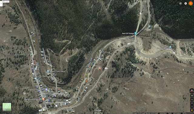
Redcliff now also shows the same sort of geometry, and can be at the other end of the layout where I need to turn the corner again. Much of the town is now in the foreground, but there are a few significant buildings that will be modeled in this arrangement.


The next view is around Silver Gulch, as the line emerges from the Eagle River Canyon. Notable here is that while the Eagle River is in the foreground, behind the track is a small pond whihc now can easily be modeled.


The next two images are of the Camp Hale area. Highway 24 will come from the background, cross over the railroad on an overpass, and the remains of Camp Hale become a foreground scene.


East of Camp Hale, we encounter Yoder Gulch, and the railroad climbs onto the hillside. Again, the perspective works very well.


As the railroad continues east, it clings to the hillside and passes through Dean Tunnel at Pando. Again, Highway 24 is in the foreground, so the perspective of the railfan is preserved. 


Between Pando and the next major element is Bennet Gulch, which is just a more nondescript area where the highway and the railroad close the elevation difference.


We finally arrive now at Mitchell, where the railroad makes a series of sweeping curves across the valley to gain elevation. This element is now true to the classic railfan view.


There is not a lot left to see before we reach the summit. After Mitchell, the line and the highway climb with the valley between them. The key feature here is that the valley rapidly narrows as we approach the tunnel.


The western portal of Tennessee Pass is at the end of the valley. on a sweeping curve that would lead into another end of the layout. 


I plan to model the highway climbing over the pass, while the railroad goes underneath, so this switchback will fit into the end of the layout and with a little more bending, will bring the viewer to the other side.


On the eastern side of the pass, the East Portal of Tennessee Pass exits into the Tennessee Pass siding. This is the farthest east siding I think I will model because I want to model the helpers cutting off. One challenge that now comes to play is that the wye would exit onto the front of the layout, and the wye is on the west end of the siding. I may model it with the wye to the eastern end of the siding so as to help the transition of the mainline into the helix which will need to rotate in the opposite direction as to the direction of the climb. I did just this on the prior layout. I also took the wye, and used the tail track to connect to Leadville. While not quite correct, it allowed me to give the Leadville/Malta turn somewhere to go. It actually is closer to the configuration when there was a connection to Leadville west of Malta, but this is a minor compromise to move this connection from Malta to the siding at Tennessee Pass. The operational benefits are just too good. 

So, all in all, it looks like this configuration will work quite well. I've taken these captures and built a little guide file so that as I work on the different areas I have some references to study for the design of each scene. So, that is Google Maps as a tool to conceptualize the design of a layout area.

One of my other concerns from the previous plan was that the space was a little tight to make everything work. But I have been considering that issue as well. My next post will focus on the plan to resolve those issues, and will define the footprint of the layout plan. 

Update: Just to maintain a little continuity here, I am still working on the T Layout, the HOn2Z cars, and the FMC4200 Hopper prototypes. I haven't forgotten those projects, and will post updates periodically in between layout planning updates.