

 |
| UP7085 leads a train west through Coal Creek Canyon towards Tunnel #1. Photo by John Crisanti. |
Subscribe To
Wednesday, September 25, 2019
Wordless Wednesday
Saturday, September 21, 2019
Justifying a Rework of the Layout Design?
Design is an iterative process, and sometimes the iterations are big. In the last several posts, I have repeatedly made comments that "the design is okay but..." At some point, those compromises add up, and so in the last week or so, I have begun wondering if I need to make some adjustments to the layout. Let's revisit some of the issues that have been worrying me.
One issue that I have not previously discussed, but has come up, is with how the track will meander through the second deck and even on a third deck. Let me explain.
My design concept after leaving Plain is to enter the Tunnel District with Tunnels 2-8. These tunnels are the ones that run along and through the flatiron formations, such as those in the view below.
At Tunnel 8, the railroad swings into South Boulder Canyon, and upon exiting Tunnel 8, begins to transverse another distinct region of the Tunnel District. With Tunnels 10-18 (recall that Tunnel 9 has been daylighted, the scenery changes character. My goal here is to gain sufficient elevation in this climb back around the peninsulas so that when I reach the doorway, I can arc the mainline along to the wall in a 180 degree curve with a nod-under and enter the siding of Crescent. Leaving Crescent siding, the terrain again changes, and I hope to use the length of Tunnel 23 to create a narrow removable section that would pass in front of the electrical boxes and reach a third deck above the Big 10.
On the third deck, the climb continues, with Tunnels 23-27 and Tunnel 29 finishing the climb into the siding at Cliff. Leaving Cliff, we encounter lonely Tunnel 30, and then the sidings of Rollins, Tolland and East Portal before reaching the Moffat Tunnel. While I could end the line at the summit, I dearly like the idea of representing Winter Park and at least Tabernash, critical towns on the western side of the Moffat Tunnel for the operation of the Ski Train. The Ski Train stops in Winter Park (while Amtrak stops in Fraser and then Granby - towns before and after Tabernash) and the Ski Train equipment is turned at Tabernash and either waits there or in Fraser until its afternoon departure. So, while I see little hope of reaching Bond with its crew change point, Tabernash seems achievable.
In short, I have become convinced that there are elements of the benchwork configuration that are not working well in this plan. So, I have decided to revisit the benchwork configuration for a portion of the plan as shown below.
Time to iterate on the design. The nice part about drawing these plans up using a computer-aided design (CAD) system is that you can save files and iterate. So, I can leave the plan where I am at, and play with some alternatives. If none of the alternatives seem to work out better, I can go back and continue with the plan as it is currently defined. Or, if I find another solution worth pursuing, I can go from there. So, I'm going to work generating some alternatives to the problems above so that I can continue to go Thru the Rockies and Not Around Them in 1:160!
Cameron Turner
- Previously, I worried a bit about the height difference between the track at Rocky and the track above it passing through Blue Mountain Crossing. The clearance from the track to the bottom of the upper deck is about 6 inches, which once mocked up, appears feasible albeit not perhaps ideal.
- Similarly, I worried about the lack of distance between the west end of Rocky siding and the east end of Clay siding.
- I also expressed some concern with the length of the siding at Plain, wondering if it could be a bit longer.
- Finally, I continue to be bothered by the support post near Plain, wondering if I could find a better bench work configuration to make the location of this post less obnoxious.
One issue that I have not previously discussed, but has come up, is with how the track will meander through the second deck and even on a third deck. Let me explain.
 |
| Concept for the trackage on Deck 2. |
 |
| A UP train works its way east through the Flatirons of the Front Range. Photo from 7ideas Productions. |
 |
| Concept for the trackage on Deck 3. |
- But looking at these plans, another set of issues appears to be pressing. Plain, Cliff and Rollins are all mashed into the same aisle space. And if we include the first deck, we would find Chem Spur and C&S Junction are also stuck there. Already a narrow aisle, this seems destined to get plugged up with operators.
- The helix intended to connect to the Rocky Flats branch is also a potential problem. Where it loops around by Leyden, the branch line is actually well above the height of Leyden, yet there is not a lot of space there between the tracks. The result appears to be a near vertical backdrop between the tracks. Further, the radius of the helix is less than I would like it to be which also drives up the grade.
- Furthermore, looking at deck 2, Tunnel 2 is going to fall at the curve leading along the wall. Exiting Tunnel 2 is Bull Gulch, a sweeping curve viewed from the inside, between Tunnels 2 and 3. This feature is going to be difficult to model.
- In addition, the flatirons would be on the opposite side of a narrow aisle from the scenery of the middle tunnel district (Tunnels 10-18), which when I picture it, is mentally jarring.
- Finally, I am a little concerned as to whether there is sufficient distance for the middle tunnel district to conclude before I need to reach Crescent opposite the door. And that position is needed to allow for Tunnels 19-23 to occur to place Tunnel 23 in front of the electrical boxes.
In short, I have become convinced that there are elements of the benchwork configuration that are not working well in this plan. So, I have decided to revisit the benchwork configuration for a portion of the plan as shown below.
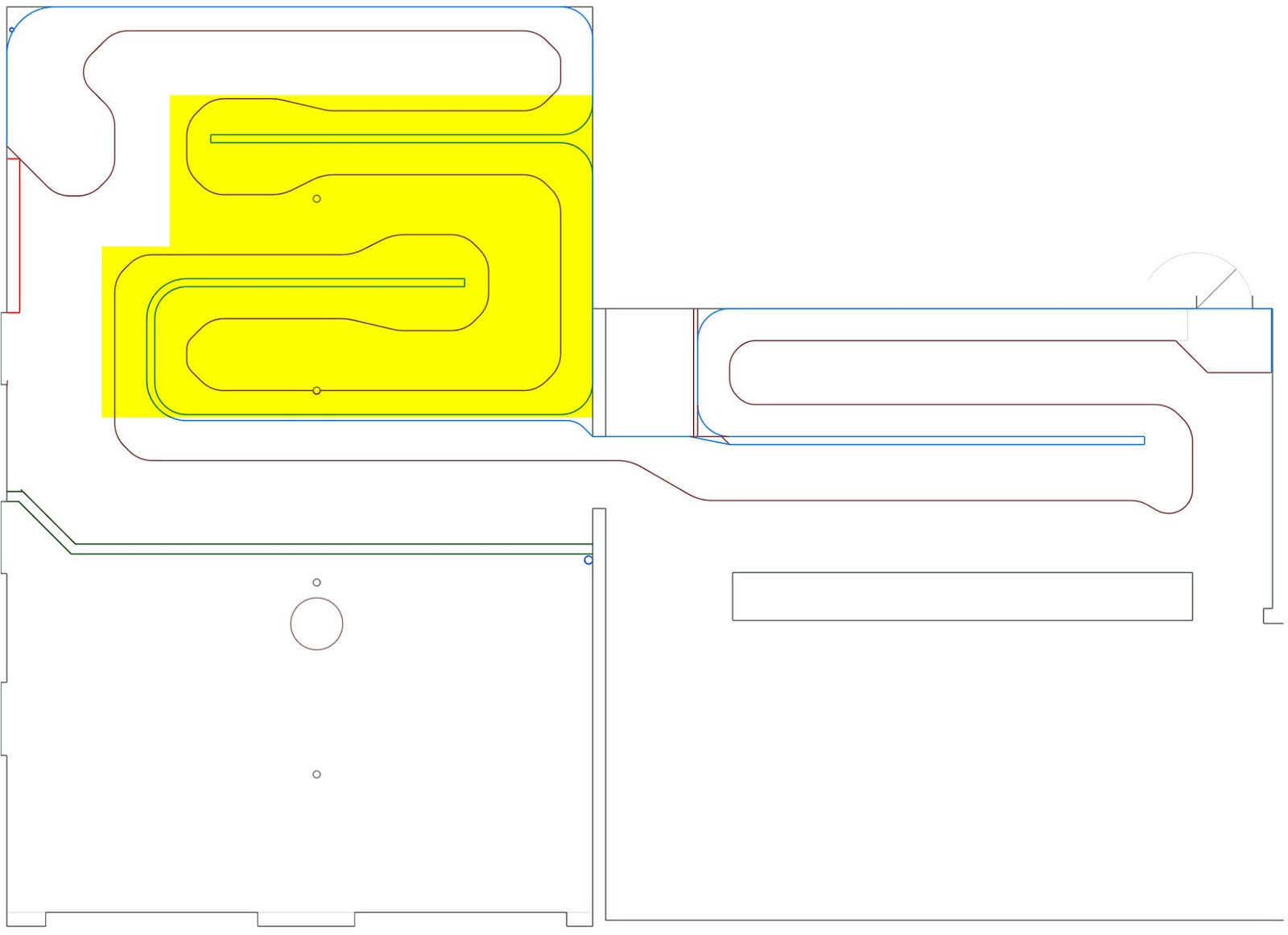 |
| I plan to try to reconfigure the benchwork in the highlighted areas. |
Cameron Turner
Wednesday, September 18, 2019
Wordless Wednesday
 |
| Clay Siding with Amtrak #42 leading the California Zephyr West. Photo by John Crisanti. |
Monday, September 16, 2019
A Place with a View
After Tunnel 1, the DRGW takes a pause to gather itself for its next assault on the front range. The grade moderates as the main line enters an area known as Plainview where the DRGW located Plain Siding. The scenery however is anything but plain. From this perch, there are extensive views of the plains to the east with Denver in the foreground. To the west of the mainline, numerous homes have been built to enjoy this view. The neighborhood is small, but is well connected to the railroad as many of the families have ties to the DRGW.
However, the siding of Plain (MP 24.5) is the center of railroad action. At a length of 6530 feet, Plain is a common meeting point for trains on the Moffat. It has easy access in the event that crews need to be pulled off a train due to service hour rules and helps provide a relief valve for traffic through the Big 10 curves. It is also home to a house track and it is common to see maintenance of way crews using Plain as a location to access the mainline to work between Plain and Crescent siding (MP 31.2).
Cameron Turner
 |
| This is typical of the views from houses above Plainview. |
 |
| UP 5613 in Plain Siding. Note the MOW equipment in the house track. Photograph by John Crisanti. |
Plain siding has been lengthened over the years, and so at
its western end lies Rainbow cut, where the main line passes through a colorful
cut of rock as the siding wanders to the west.
 |
| DRGW 3121 leads Amtrak's California Zephyr through Rainbow cut on March 4, 1984. Photo by John Benner. |
The track plan for Plain siding runs down the opposite side
of the peninsula from Tunnel 1. My version of Plain has a little more curvature
to it than does the prototype, but like the prototype it serves to have a pause
in the climb. The elevation of Plain is +22.5” above the reference elevation
(Prospect Junction) and the track below in Barbara Gulch lies at an elevation
of about +5”, so the climb has been effective at creating a second deck. Plain
siding works out to be about 140”, a bit less than Rocky or Leyden, and in fact
a little less than a typical coal train.
 |
| Track plan for Plainview including Plain Siding. |
Cameron Turner
Saturday, September 14, 2019
Into the Tunnels: Tunnel 1
The Moffat is known for the tunnel district. Between Denver and the Moffat Tunnel, a distance of 50 miles by rail, there are 28 tunnels. These are clustered in a span of 17.3 miles, starting with Tunnel 1 (MP 23.2) and ending with Tunnel 30 (MP 40.5). (Note that Tunnel 9 and Tunnel 28 no longer exist.) This series of tunnels and the regions through which they take the Rio Grande is one of the major reasons for my interest in the line.
Tunnel 1 is 299 feet
long, or 22 inches in N-scale. Indeed, it could be modeled in full scale at
that size. However, as I worked on developing track plans to model the tunnel
district, I found that while some tunnels could be modeled at scale (Tunnel 29
is only 78 feet long), others would be challenging (Tunnel 17 is 1730 feet
long). Early on, I adopted a goal to model the tunnels using a formula so that
the shortest tunnels would be full scale, while the longest tunnels would be shortened
to something more reasonable. Using this formula, I established the following
goals for modeling each tunnel, as shown below.
Cameron Turner
 |
| Caboose 01460 rolls by while a gaggle of SD45s pulls the train into Tunnel 1 on the far side of Coal Creek Canyon. Photograph by Chuck Conway. |
The tunnels at the ends of the district are orphans. They
are different from the rest of their siblings. Tunnel 1 allows the main line to
withdraw from its first encounter with the front range and retreat to climb
along the Flatirons that make up this barrier. Indeed, there are 2 miles
between Tunnel 1 and Tunnel 2. Furthermore, one could also argue that it is a
full 3.5 miles before the railroad once again tries to thrust its way into the
mountains like it does in Coal Creek Canyon. Tunnel 1 is a prologue to what is
coming, and Tunnel 30 is a reminder of what the railroad has gone through to
get there.
 |
| Table of the actual versus target design lengths for the layout tunnels. |
I am pleased to note that the median (0.84) and average (0.83)
compression ratios are very similar. Furthermore, the target tunnel lengths all
maintain the rank ordering of tunnels in terms of their length. Several tunnels
(4, 7, 22 and 29) have little or no compression, while the longest tunnels (10,
17, and 23) all are much more palatable in terms of length. For instance,
tunnel 10 would be 117.9” long at full scale, but its target design length is
now 75.46”. At a little more than 6 feet long, that is still a long tunnel, but
many trains will still be long enough to be visible while in the tunnel. If
modeled to full scale, that would not be the case. Yet, a six foot tunnel still
garners the feel of an immense tunnel.
Tunnel 1 is the first tunnel to transverse a sand and pebble
conglomerate that forms the backbone of the flatirons. The flatirons are up thrust
sedimentary slabs that form a picturesque backdrop to Boulder, Colorado. The railroad
east and west portals are both concrete with sprayed concrete and gunite added
in between to maintain the stability of the tunnel. The exterior of the rocky
outcrop through which the tunnel passes is dotted with ponderosa pine trees. Based
on the target length for Tunnel 1, the model should be approximately 20 inches
in length, about 89% of the full-scale tunnel length but still substantial.
 |
| Plan for the Tunnel 1 area. |
Just to the railroad west of Tunnel 1 is a grassy area where the mainline curves around as it prepares to swing around to the north and enter a flat spot known as Plainview. I positioned Tunnel 1 to allow for this curve while achieving the target design length of 20" which works out to be about 267 scale feet. This is very close to the target length. This last stretch of main line also brings to an end the steepest climb on the railroad. Just as on the real thing, the main line grade moderates at Plainview as the line enters Plain Siding, but more on the design of Plainview in another post.
Cameron Turner
Wednesday, September 11, 2019
Wordless Wednesday
 |
| The Big 10 Curves at night with Amtrak #169 leading the California Zephyr east to Denver. Photo by John Crisanti. |
Tuesday, September 10, 2019
The Turning Point – Part 4: Coal Creek Canyon
Continuing up the hill from Clay where we left off in the previous post of the series, the railroad first curves into the mouth of Coal Creek Canyon (now heading west) which it uses to execute another 180 degree turn to once again head east out of the mouth of Coal Creek Canyon, before encountering Tunnel #1 and swinging back to the north to reach the site of Plainview. As part of the continuing climb to separate the two decks of the railroad, two significant scenes are worth modeling before we reach Tunnel #1.
Blue Mountain Drive is the first stop along this climb and is a common photo spot. Especially if you can shoot from the north side of the tracks which allows you to catch the train as it climbs up the canyon. However, the light is better from the south, but this means you have to wait for the train to cross to move on to the next set of shots, which usually means heading to Plainview. Of course, if you are catching an eastbound, you can continue into the development and climb up on the ridge above the Big 10 Curves to get some long range shots of the train descending through Clay, the Big 10 and Rocky below you. Nonetheless, Blue Mountain is a railfan spot that you almost must have. Just a simple crossing.
Further up the canyon, the intensity increases as the line makes its loop around the rapidly narrowing canyon. The loop crosses over Colorado Highway 72 on a deck girder bridge, and a Colorado Department of Transportation Sanding Facility (for loading salting and sanding trucks in the winter) is located within the loop. The grade continues in this region at a steady 2% and the canyon echos with the engines straining to climb the grade.
This is an ideal scene for a walk-in effect, and so it makes a lot of sense to try to locate it at the far end of the aisle from the Big 10 Curves. With this in mind, the resulting plan for these features is shown below.
A few notable comments on this part of the plan. As discussed last time, the second deck bench initially provides about 6" of clearance from the track at Rocky to the lower edge of the upper deck bench work. Not a lot, but at least in the mock up, it appears workable. The track continues to climb, gaining another 3/4" in elevation by the time it reaches the area proposed for the Blue Mountain grade crossing, reaching an elevation of +19.5" inches at the bridge over Colorado Highway 72 in the upper reaches of Coal Creek Canyon. At this point in the scene it is important to remember that the roadway will be closer to an elevation of +18" as it goes under the tracks, and the bottom of the bench work will be closer to +16". Below, the track is at about +8", but this is where US Highway 93 crosses over the mainline, which will be at about +10". US Highway 93 then has a grade crossing with the Rocky Flats branch (also +10"). This means that even in this area, my clearance is about 6".
The plan does allow for a broad 26" radius curve through the 180 degree return loop, which should look very much like the effect of the loop in the photo above. By the time the line is heading east out of the mouth of Coal Creek Canyon, the main line has climbed to an elevation of +20.5", while the main line below (located in Barbara Gulch) is at approximately +7.5". We have climbed 13"over a run of about 68', or more than 2 scale miles. Because of the flat grade in Rocky, that works out to be an average grade of 1.5%. In the Big 10 Curves, I reached a maximum grade of 2.5% (slightly over the 2% grade of the real thing) but allow that grade to drop to 2% in Coal Creek Canyon. I could play with these grades a little more to try to adjust deck heights, but this looks like it will work, although I will likely try to tweak things a little more before the design is complete.
Cameron Turner
 |
| BNSF Dash 9-44CWs 1006, 4944 & 4014 climb towards Blue Mountain Drive Crossing in Coal Creek Canyon. Photo by Andrew Naylor. |
Further up the canyon, the intensity increases as the line makes its loop around the rapidly narrowing canyon. The loop crosses over Colorado Highway 72 on a deck girder bridge, and a Colorado Department of Transportation Sanding Facility (for loading salting and sanding trucks in the winter) is located within the loop. The grade continues in this region at a steady 2% and the canyon echos with the engines straining to climb the grade.
 |
| From high above Coal Creek Canyon, you can see the entire loop and the east portal of Tunnel #1. Photographer unidentified. |
 |
| Track plan for the region including Blue Mountain Drive and the 180 degree curve at the upper end of Coal Creek Canyon. |
The plan does allow for a broad 26" radius curve through the 180 degree return loop, which should look very much like the effect of the loop in the photo above. By the time the line is heading east out of the mouth of Coal Creek Canyon, the main line has climbed to an elevation of +20.5", while the main line below (located in Barbara Gulch) is at approximately +7.5". We have climbed 13"over a run of about 68', or more than 2 scale miles. Because of the flat grade in Rocky, that works out to be an average grade of 1.5%. In the Big 10 Curves, I reached a maximum grade of 2.5% (slightly over the 2% grade of the real thing) but allow that grade to drop to 2% in Coal Creek Canyon. I could play with these grades a little more to try to adjust deck heights, but this looks like it will work, although I will likely try to tweak things a little more before the design is complete.
Cameron Turner
Sunday, September 8, 2019
The Turning Point Part 3: Rocky, the Big 10 and Clay
To complete the design of the Layout Design Complex (LDC) that is formed by the layout design elements of the exit from Barbara Gulch under the US-36 bridge, the siding and junction of Rocky, the Big 10 Curves, and finally the siding of Clay, there needs to be an analysis of the grades to determine if they are effective in providing the transition between layout decks. To read the previous entries about the LDC (Part 1) and the design of the LDC (Part 2) see those blog entries.
Not knowing what the elevation of my low point of the layout will be relative to the floor, I planned this layout with a low point set at Prospect Junction near the crossing of the South Platte River. The line climbed around through North Yard, achieving a climb of +2.5" by the time that the main line reached Utah Junction. The climb continues, just as in the prototype on 1% or less grades through C&S Junction, Arvada, Leyden and Barbara Gulch. By the time the main line reaches the bridge carrying US-36 over the railroad, and enters Rocky, the main line has climbed to +8.5" over the reference point at Prospect Junction.
I made the decision to provide a flat spot in Rocky up until the point where the Rocky Flats branch joins at Rocky Junction. From here, I have the main line climb, slowly at first, but with the grade growing. The prototype grade becomes 2%, but I found that I needed a little stiffer grade to achieve the desired elevation climb. In the end, I settled on 2.5%, with the turnouts not included, so the actual grades will be a little less. By the time the main line reaches the west end of Rocky siding, the main line has climbed to +9.6". The main climbs another inch by the time the Big 10 windbreak is reached, and to +11.63" by the time that the wind break ends. The line reaches +12" by the time that Clay siding starts, a climb of +3.5" from where the line entered Rocky. The climb continues through Clay, reaching +14.75" by the west turnout.
At this point, my vertical clearance is 5.75" rail head to rail head. In N-scale, minimum clearance as specified by the NMRA is 1.72", and I treat it as 2". So, at this point, I do have about 4" of clearance from the top of the lower train, to the rail head of the upper main line. If I subtract out a minimum of 2" for a thickness of the bench work, that leaves only 2" which is not enough. Fortunately, I can keep the mainlines from crossing each other for a while, allowing me to climb to an elevation of +16.5" almost directly above Rocky Junction (located at an elevation of +8.5"), which allows me to double the clearance between the top of the equipment on the lower deck and the bottom of the upper deck. Is this enough? Time for a mock-up to see how it looks.
I used an adjustable bookshelf to create a simple mockup of the bench work where the two levels overlap. The plan has the depth of the bench work at this region set as 12 inches, and, and my bookshelf is only 11", but it gives you a good idea. With a few clamps to hold a strip of wood to simulate the full thickness of the bench work, and a few binder clips to place a couple of led strip lights under the bench work to provide light, I proceeded to arrange a couple of pieces of Kato Unitrack and a couple of 60' Atlas N-scale passenger cars I had handy into the scene. My conclusions:
Another design concern is as to whether the Big 10 Curve is large enough to feel realistically "large" versus a train. A typical coal train may be about 13.5' long. Laying out such a train through the Big 10 Curve shows the following.
As the train enters Clay, its tail would still be in Rocky. However, by the time the train clears Rocky, its head would be passing by it on the siding above in Clay. There should be nearly 1.8 miles between the sidings and a Moffat Coal train would be approximately 1.3 miles long. So, the sidings are a little close. But does it give the right feel? I think it is pretty good, but if possible, a little more length would be good to include between the sidings.
My conclusion - the plan is nominally workable, but should be revisited. The plan can continue onto the second deck, but further consideration may be necessary to see if some additional improvement can be achieved to increase the deck separation, manage the viewing height, and lengthen the distance between Rocky and Clay. While 1.8 miles (about 59') is probably impractical, perhaps something greater than 13.5' should be targeted.
Cameron Turner
Not knowing what the elevation of my low point of the layout will be relative to the floor, I planned this layout with a low point set at Prospect Junction near the crossing of the South Platte River. The line climbed around through North Yard, achieving a climb of +2.5" by the time that the main line reached Utah Junction. The climb continues, just as in the prototype on 1% or less grades through C&S Junction, Arvada, Leyden and Barbara Gulch. By the time the main line reaches the bridge carrying US-36 over the railroad, and enters Rocky, the main line has climbed to +8.5" over the reference point at Prospect Junction.
 |
| Main line climb through the Rocky-Big 10-Clay LDC. All elevations are relative to the height of Prospect Junction. |
At this point, my vertical clearance is 5.75" rail head to rail head. In N-scale, minimum clearance as specified by the NMRA is 1.72", and I treat it as 2". So, at this point, I do have about 4" of clearance from the top of the lower train, to the rail head of the upper main line. If I subtract out a minimum of 2" for a thickness of the bench work, that leaves only 2" which is not enough. Fortunately, I can keep the mainlines from crossing each other for a while, allowing me to climb to an elevation of +16.5" almost directly above Rocky Junction (located at an elevation of +8.5"), which allows me to double the clearance between the top of the equipment on the lower deck and the bottom of the upper deck. Is this enough? Time for a mock-up to see how it looks.
 |
| Mockup of the two levels with an 8" rail head to rail head height and a 2 inch bench work thickness. |
- Without the led lights, the lower deck is clearly too dark. And the viewing height versus eye level will be crucial. The shelves I used were lower than the likely layout height at this transition, but there is clearly a relationship.
- Surprisingly, the height is workable. You can get your hand in to fix a derailed car if necessary, provided that the shelves are not too deep. The scene is also helped by not having foreground structures that reach the bottom of the upper deck.
- It is also apparent that the lower level works best if the scenery intended to be viewed during operation is closer to the front. This will also help the lighting needs of the layout.
 |
| Another view from a higher viewpoint and with the lower level track about 6 inches back into the scene. |
Another design concern is as to whether the Big 10 Curve is large enough to feel realistically "large" versus a train. A typical coal train may be about 13.5' long. Laying out such a train through the Big 10 Curve shows the following.
 |
| A 13.5' Coal train (In Orange) through the Big 10. |
My conclusion - the plan is nominally workable, but should be revisited. The plan can continue onto the second deck, but further consideration may be necessary to see if some additional improvement can be achieved to increase the deck separation, manage the viewing height, and lengthen the distance between Rocky and Clay. While 1.8 miles (about 59') is probably impractical, perhaps something greater than 13.5' should be targeted.
Cameron Turner
Friday, September 6, 2019
The Turning Point Part 2: Rocky, the Big 10 and Clay
So, given all the information in Part 1 of our discussion of the design of the Rocky, Big 10 and Clay Layout Design Complex, what can we make out of it to form a design? Fortunately, all the twists and turns of the line exiting Barbara Gulch, Rocky, the Big 10 and Clay really do resemble a toy train layout which twists and turns back on itself, climbing steep grades. As this part of the layout is intended to transition from one deck to a second deck, this is to my advantage, and indeed, since the first days that I started considering a layout of this area, I fell on the idea of using this set of layout design elements, the collection of which I am referring to as a Layout Design Complex (LDC), as a deck transition point. As part of my effort to design the LDC, I began with a full scale drawing of the area.
Obviously, at a massive 19' by 62', there is little hope of modeling the complex in full scale. But here I can note a few things. First, the 10-degree curves work out to be a 43 inch radius in N-scale, and I plan to model this with a 19.375" radius or 45% of full scale. Second, my target train length is also about 33% of full size, so, a 1/3rd scale model might be more appropriate. This reduces the size to about 10' by 21'. So, now I fit within my room. With a little twisting of the layout, I could end up with a more suitable configuration that looks a bit more like the drawing below.
This plan is now about 8' by 21', and with a little more work, begins to resemble the configuration that I have room for in the bench work. This in turn led to the following plan.
The resulting plan generally resembles the actual geography of the area. Rocky Siding ends up with a 17' siding, and Clay ends up with an 8' siding. Just as in the prototype, Rocky is a fairly long siding, and Clay will be a short siding, generally useful only for passenger trains. The Rocky Flats branch enters the main line at Rocky, connected with a 4% grade to enable a grade crossing of US-93 just beyond the bridge that carries the highway over the mainline. However, shortly after this crossing, I will need to arrange for the line to disappear from the scene so that it can connect to a helix leading to either the modeled branch or a staging yard for the branch.
There is also one challenging room constraint. As can be seen on the lower left hand corner, there is the electrical boxes for the house (in red) that will intrude on the Big 10 scene. Generally, I think this configuration is manageable. I can certainly open the boxes and manipulate the fuses in the space available. Should complete access be needed to the boxes, I plan to design the Big 10 to ride on a rolling table. The piece of bench work between the dotted lines will be removable, and will include the deck over deck transition, so that the remaining table with the Big 10 curve on it, can be rolled away from the wall. This should allow access to the electrical fuse boxes.
Conceptually, in 2D, the plan appears viable, but now the question becomes "Will it work in 3D?" In other words, can I achieve a reasonable deck over deck separation to make the scene work? And what is a reasonable deck over deck separation anyways? So finally, the estimation of the grades necessary becomes important.
Cameron Turner
 |
| A Full Sized N Scale Model of the Big 10 Layout Design Complex. |
 |
| Squeezing and twisting the mainline, while reducing the size to about 1/3rd of full-size, yields a much more manageable plan. The biggest difference is that the main line to Plainview will twist onto the second deck above Rocky, transitioning somewhere near the northern part of the Little 10 curve. |
 |
| Layout Plan for the Rocky-Big 10-Clay LDC. |
There is also one challenging room constraint. As can be seen on the lower left hand corner, there is the electrical boxes for the house (in red) that will intrude on the Big 10 scene. Generally, I think this configuration is manageable. I can certainly open the boxes and manipulate the fuses in the space available. Should complete access be needed to the boxes, I plan to design the Big 10 to ride on a rolling table. The piece of bench work between the dotted lines will be removable, and will include the deck over deck transition, so that the remaining table with the Big 10 curve on it, can be rolled away from the wall. This should allow access to the electrical fuse boxes.
Conceptually, in 2D, the plan appears viable, but now the question becomes "Will it work in 3D?" In other words, can I achieve a reasonable deck over deck separation to make the scene work? And what is a reasonable deck over deck separation anyways? So finally, the estimation of the grades necessary becomes important.
Cameron Turner
Wednesday, September 4, 2019
Wordless Wednesday
 |
| On February 4, 1984, Train #187, a Priority Freight is led by DRGW5336 out of Rocky into the Big 10 Curves by John Rus. |
Tuesday, September 3, 2019
The Turning Point – Part 1: Rocky, the Big 10 and Clay
Everything up to this point has been but a prelude to the DRGW assault on the Rockies. This assault begins with the siding of Rocky (MP 18.0) at the foot of the Big 10 Curves. Rocky is a 7330 foot siding with a house track and the junction with the Rocky Flats branch. The Rocky Flats branch is the last significant industrial work east of the Moffat Tunnel. On the main line, to the west of Rocky, lies the Big 10 Curves, a series of 10-degree railroad curves (radius of about 574 feet or 43 inches in N-scale) along the inside of a natural amphitheater and then along the outside of a bluff that allows the DRGW to gain critical elevation for its assault of the front range of the Rockies. The line which up to this point was nominally headed west, swings towards the north, then 270 degrees back through the south to the east, and then another 180 degrees to the west, before another 90 degree swing to bring it to the north, and into the 5780 foot siding of Clay (MP 21.2).
Looking at the area on Google Maps gives another view. The main line enters from Barbara Gulch and crosses under the US Highway 36, running between Golden and Boulder, and enters Rocky Siding.
Rocky extends into the natural amphitheater, providing a significant siding for trains to pass, as well as serving the junction to the Rocky Flats Branch. That branch leaves Rocky on a 4% grade to climb to a grade crossing across US-36, and then CO Highway 72, as it heads north along US-36. Exploring the area with Google Earth in 3D yields a number of interesting views.
Wrapping along the lower bowl, also called the Little 10 Curve, the mainline climbs on a 2% grade before reversing course to climb around the outside of a bluff that forms the Big 10 Curve. Trains on this bluff are protected from the high winds that can exist in the area by a set of abandoned hopper cars welded to a set of rails on the inside of the curve. Nature has overgrown many of these cars.
More details about the windbreak can be found here. Past the windbreak, the line turns and enters Clay siding. Originally named Fireclay for the clay mined in the area and used to make bricks, the siding name was shortened to Clay. Today, it has been renamed Eisele for a UP official. The siding is short, and thus rarely used. Furthermore, the siding itself is on "soft" ground, and hence its use is restricted to light trains. I've only seen it used for passenger trains to pass freight trains. All in all, each of these three elements are a fundamental component to modeling the area.
Cameron Turner
 |
| Looking over the Big 10 Curves facing southeast. That is Denver in the distance, with Clay siding in the foreground. Rocky siding is just to the left of the picture on the lower level of the loops. Photo by David Langdon. |
 |
| Rocky Siding - the Big 10 Curves - Clay Siding from Google Maps. |
 |
| A train led by UP6773 leaves Rocky east bound for Barbara Gulch. The snow cleared out of the upper and lower loops forming the Big 10 can be seen in the background. February 8, 2012 by Cameron Turner. |
 |
| UP5715 leads a train under the US-36 bridge into Rocky Siding, June 4, 2015 by Cameron Turner. |
 |
| Google Earth View looking south west. The Rocky Flats branch exits to the lower right hand side of the picture, while the mainline to Barbara Gulch exits the lower left. The mainline headed west exits along the upper right hand side of the image. |
 |
| Another Google Earth Image looking north. In this view, Barbara Gulch exits the lower right hand side, and the upper Big 10 curve is on the left side of the image. |
 |
| Installed in November or December of 1971, a string of hopper cars filled with dirt made a suitable windbreak to protect cars from high winds in the area. Photo by Ray Kenley. |

 |
| Even the dirt in the cars has proven to be a suitable place for grasses and weeds to grow. Photo by Loco Steve. |
 |
| Google Earth view of the windbreak. Here, the hopper cars are vague rectangles of foliage. |
Cameron Turner
Subscribe to:
Posts (Atom)