

 |
| North Yard Looking North in 1979. |
Subscribe To
Wednesday, July 31, 2019
Monday, July 29, 2019
North Yard
Yards are one of my favorite items to operate on a layout. So, I have developed some definite preferences for a yard. If space and traffic allow for it, I prefer double-ended yards, particularly if I have multiple switch engines working. This way, each can have a yard ladder to work, and any track can become a thru track as needed. Yard leads that do not interfere with mainline operations are nice, but I find the often presented rule that the lead should be as long as the longest track to be a bit unnecessary. Frankly, I don't often classify blocks of 30 or 40 cars in one pull. not only does it often overpower the engines, but it also tempts fate in pushing and pulling strings back and forth through turnouts. I prefer to have leads of at least a reasonable length, maybe 10-12 cars, and I am not unhappy if they are longer, but I do not buy into the leads needing to be as long as the yard. Finally, I avoid double slip switches like a curse. While they look nice, I see too many derailments and too many crews fussing with them to get them right.
The DRGW North Yard was built in 1948 as a primary classification yard several miles north of the original Burnham Yard and Shops complex.
The whole yard is about 26 tracks wide with an engine servicing facility on the south (left above) end of the yard and a TOFC yard next to the Cargill elevator on the north end. To the east (bottom) is the BN TOFC facility and also to the south is Renneck Yard. I wanted my model to be substantial enough to produce the mass of the a classification yard, so one decision I made was to make the BN TOFC facility a joint operation with the DRGW.
One of the main features of North Yard was that this was a crew change point for coal off the Moffat to be either interchanged to head east (via BN or UP), or to be routed south over the joint line to be routed either to Kansas City, or to be interchanged there to head south to Texas. So, I wanted the yard to be long enough to also handle a coal train. I mocked up a number of coal trains, and settled on a target coal train length of 36 cars with five engines. Three of the engines will be on the point, and two will be a swing helper set on the rear. This results in a train about 15 feet long in N-scale. This length became my target design length for a coal train. I'd like it to be a bit longer, but that may not be feasible in many cases. Furthermore, I wanted to include engine servicing on the south end of the yard, the signature Cargill elevator to the north end, and the signature Denver North Yard Tower at the south end of the yard (at full scale).
My plan has 13 classification tracks, and 4 of these tracks are long enough for my target coal train length, although I may need to cut off the swing helpers to clear the ladders. I was also able to replicate a number of the spurs associated with the engine fueling facility on the south (right) side of the plan. Another schematic of these tracks proved useful to that effort. I still have some details to work out in this area.
I ended up adding a slight bulge to the benchwork on the right hand side to allow for a a full sized model of the North Yard tower to be included. This is another one of the full scale size structures I want on the layout. In fact, I plan to place one or more cameras in the tower so that the yard operations can be viewed on a monitor from the dispatcher's office.
The left hand side of the yard narrows so that the layout can pass through the existing doorway to the garage area. This doorway will divide North Yard from the Cargill Elevator complex. However, before I pass through the doorway, I need to include Utah Junction. Utah Junction provides a connection to the industrial north end of Denver, as well as the connection to the UP and until its demise, the Rock Island at Sandown Yard. Multiple locals could be sent out each day to the Belt Line, so it provides a significant amount of switching traffic in Denver. Furthermore, the crossings over the DRGW and BN mains are a signature design element at this end of North Yard. So, I worked them in by allowing a 15" minimum radius on this secondary trackage.

The crossings are 30 degree crossings, so they should be relatively robust mainline crossings. However, in order for this to work, it does mean that Utah Junction needs to be about 2.5" above the track at the start of south end of Renneck Yard. This allows the track exiting Utah Junction to come in above the Denver Union Terminal trackage serving Union Station, which is enough elevation difference to be one loop up in the helix. This can be accomplished with less than a 1% grade starting at the south end of Renneck Yard, and proceeding to Utah Junction. This means that both yards will likely have some grades in them, but that too is prototypical. In 2007, there was a runaway set of cars that destroyed two engines in the BN 31st Yard (to the south of North Yard).
Okay, not exactly the yards I am taking about, but nonetheless, these yards are all built come out of the South Platte River Valley - nearly flat, but not quite.
One last thing to note, I have allocated trackage to Caboose tracks, despite my 1987-1996 era. Generally, at this point most trains would not have cabooses. And I am a little undecided about whether I will limit my cabooses to the locals, or still use them on all trains. There is an argument to be made that it is plausible for cabooses to have run a few years longer on the trains through the Rockies, so I figure as I like them, I will at least leave tracks for them.
All told, my plan for North Yard has a capacity for 564 50' freight cars with 13 classification tracks. At 50% working capacity, that means that there will likely be close to 300 cars in the yard at any one time. I think that this will definitely capture the feel of a large classification yard.
Cameron Turner
The DRGW North Yard was built in 1948 as a primary classification yard several miles north of the original Burnham Yard and Shops complex.
 |
| Schematic of North Yard from Railblazer. |
One of the main features of North Yard was that this was a crew change point for coal off the Moffat to be either interchanged to head east (via BN or UP), or to be routed south over the joint line to be routed either to Kansas City, or to be interchanged there to head south to Texas. So, I wanted the yard to be long enough to also handle a coal train. I mocked up a number of coal trains, and settled on a target coal train length of 36 cars with five engines. Three of the engines will be on the point, and two will be a swing helper set on the rear. This results in a train about 15 feet long in N-scale. This length became my target design length for a coal train. I'd like it to be a bit longer, but that may not be feasible in many cases. Furthermore, I wanted to include engine servicing on the south end of the yard, the signature Cargill elevator to the north end, and the signature Denver North Yard Tower at the south end of the yard (at full scale).
 |
| Denver North Yard Plan. |
 |
| DRGW North Yard Fuel Track Schematic. |
The left hand side of the yard narrows so that the layout can pass through the existing doorway to the garage area. This doorway will divide North Yard from the Cargill Elevator complex. However, before I pass through the doorway, I need to include Utah Junction. Utah Junction provides a connection to the industrial north end of Denver, as well as the connection to the UP and until its demise, the Rock Island at Sandown Yard. Multiple locals could be sent out each day to the Belt Line, so it provides a significant amount of switching traffic in Denver. Furthermore, the crossings over the DRGW and BN mains are a signature design element at this end of North Yard. So, I worked them in by allowing a 15" minimum radius on this secondary trackage.
The crossings are 30 degree crossings, so they should be relatively robust mainline crossings. However, in order for this to work, it does mean that Utah Junction needs to be about 2.5" above the track at the start of south end of Renneck Yard. This allows the track exiting Utah Junction to come in above the Denver Union Terminal trackage serving Union Station, which is enough elevation difference to be one loop up in the helix. This can be accomplished with less than a 1% grade starting at the south end of Renneck Yard, and proceeding to Utah Junction. This means that both yards will likely have some grades in them, but that too is prototypical. In 2007, there was a runaway set of cars that destroyed two engines in the BN 31st Yard (to the south of North Yard).
Okay, not exactly the yards I am taking about, but nonetheless, these yards are all built come out of the South Platte River Valley - nearly flat, but not quite.
One last thing to note, I have allocated trackage to Caboose tracks, despite my 1987-1996 era. Generally, at this point most trains would not have cabooses. And I am a little undecided about whether I will limit my cabooses to the locals, or still use them on all trains. There is an argument to be made that it is plausible for cabooses to have run a few years longer on the trains through the Rockies, so I figure as I like them, I will at least leave tracks for them.
All told, my plan for North Yard has a capacity for 564 50' freight cars with 13 classification tracks. At 50% working capacity, that means that there will likely be close to 300 cars in the yard at any one time. I think that this will definitely capture the feel of a large classification yard.
Cameron Turner
Wednesday, July 24, 2019
Wordless Wednesday
 |
| DRGW134 switches in front of North Yard Tower on June 15, 1986. Photo byJohn Rus. |
Taken from the 48th
street overpass, DRGW143 switches North Yard. Behind is the North Yard Tower
(as seen from the Southeast).
Cameron
Turner
Monday, July 22, 2019
A Momentary Aside – The B&O Museum
Just an aside from the discussions of the layout. My wife and I took some time off to go see her parents and our nephew in Maryland. His dad and granddad are doing a good job introducing him to trains, but we decided to help out with a trip to the B&O Railroad Museum in Baltimore. It is definitely worth the stop in Baltimore. Currently, the museum is running an exhibit about how the B&O railroaders served during World War I. One element of that display is a diorama built by Bernie Kempinski. Bernie's blog is one of those that I follow regularly. The diorama of Fins France looks just as good in person as it does on Bernie's blog.
 |
| Bernie Kempinski's diorama of Fins. |
 |
| B&O Garden Railway. |
 |
| B&O HO Scale Layout. |
 |
| One of several model display engines at the museum. |
 |
| CSX1776 - Honoring our Vets. |
 |
| CSX911 - Honoring our First Responders. |
Another part of our visit was the ride over the first mile of the B&O laid out of Baltimore and now operated by the Museum as an exhibition ride. Our engine was a restored B&O EMD GP30. The trip is 10 minutes each way but is an enjoyable part of the visit.
 |
| B&O Engine 6944. |
It was nice to see the museum again and to enjoy a little time with family. We will get back to the layout plan in upcoming posts.
Cameron Turner
Wednesday, July 17, 2019
Wordless Wednesday
 |
| DRGW 5941, DRGW 5942, and DRGW 5312 on the North Yard Fuel Track by Tom Brynas. |
Taken during the early years
following the DRGW-SP merger, these old friends came back out of storage to
make up for a power shortage. Here they await their next assignments on the
North Yard Fuel Track.
Cameron
Turner
Monday, July 15, 2019
Seeing Green at Rennick Yard
Rennick Yard is one of those LDEs that I debated including in the layout. While it is not the railroad that I am modeling, or where interchanges are made between Burlington Northern (BN) and the Denver and Rio Grande Western (DRGW), nor even the major BN Yard in Denver, it is a scene that was always a transition space between Prospect Junction and entering North Yard. I wanted that pause in a train running from Union Station towards the mountains. You can see the relationship of these elements in the map below.
In reality, my research shows that Renneck Yard primarily service the Globeville Intermodal Terminal on the east side of North Yard. So, most of the traffic is intermodal with some containers and a lot of trailers. The Gloveville facility is something I plan to include as I construct my rendition of North Yard, albeit as a "joint" facility with the DRGW and BN. Below is a satellite view focused on Renneck Yard (with North to the right).
Since the area available for the BN engine facility and the throat of the BN 31st Street Yard is fairly limited in the area near Union Station on my model (as indicated below), I decided to change the function on my version of Renneck Yard. The space I had available for the 31st Street Yard is quite narrow, and would feed trains into the platforms at Union Station. Trains bound for North Yard would never appear on this stretch, but would instead appear as if from staging. So, the BN 31st Street yard would not function like the prototype in this space. Further, even if I simply modeled the engine facility here, it would be cramped and very quickly end up against the backdrop. As this was undesirable, I decided to move some functions to Renneck Yard.
So, my version of Renneck Yard is intended to serve the following functions:
Of these five functions, the first may largely be cosmetic. I don't have room for Burnham and its associated facilities, which given the fueling tracks and facilities at North Yard, are somewhat redundant, so I wasn't going to include it in the layout. Switching local industries by the BN is realistic, as there are a number of industries served by the BN in the area, but it also provides either an extra layout job, or something that can occur asynchronously. Switching Globeville, could be done by either BN or DRGW or even both, and the interchange with DRGW prototypically occurs at North Yard. So, I could just leave it so, and have BN train run out of staging, drop of cars for the DRGW, and pick up cars for the BN. Finally, the Golden Branch, which ran out to my hometown and serves Coors Brewery, is definitely something I would like to model - and even if I cannot, I would likely work it in as a staging yard, so there will be some BN overhead traffic between Prospect Junction and C&S Junction. Having Renneck Yard take on these duties, allows that operation to be almost visibly staged. With the jobs of making up the locals to the Golden Branch, running transfers to/from North Yard, receiving cars from North Yard on DRGW transfers, switching a few industries, and running some BN overhead traffic, there is a quite good job on the layout. Of course, these jobs could all also be eliminated if crews were not available, but I like the idea of having them. At the very least, Renneck Yard provides some scenery and a reminder that Denver is a major hub of railroad interchange.
So, my representation of Renneck yard has a joint double track mainline shared by DRGW and BN, running down the front. Behind that are seven double ended yard tracks with a runaround on each end. There are isolated yard leads on each end, although on the north, that lead also serves as a switching lead and connection to Globeville. On the south end, there are four tracks for the diesel shop and four for the car shop. A dummy line comes off the main from the joint line, intending to suggest that there is more yard beyond the backdrop. Total yard capacity is 190 cars, (95 cars at 50% capacity - my desired operational capacity) excluding the shop tracks. At the north end of the yard, I have also included Fox Junction, a pair of crossovers between the dual main lines. It is a significant yard, but it is not overly large, and I think it should be about right for its envisioned usages. I don't have the industries planed out at this point, but that will come together later after the other major features of the plan are worked together.
So, looking back at the overall plan, this brings us around the top side of the peninsula on the right side of the plan. On the opposite side is North Yard, the main yard of the layout, and the next LDE to be incorporated into the layout.
Cameron Turner
 |
| Map of Denver showing the relative location of Renneck Yard. |
 |
| Satellite View of Renneck Yard in Denver. |
 |
| Initially Conceived BN 31st Street Yard Location. |
- BN locomotive servicing;
- Local Industry switching by the BN;
- Switching the Globeville Facility;
- Supporting local BN operations on the Golden Branch (if modeled); and
- providing interchange with the DRGW.
Of these five functions, the first may largely be cosmetic. I don't have room for Burnham and its associated facilities, which given the fueling tracks and facilities at North Yard, are somewhat redundant, so I wasn't going to include it in the layout. Switching local industries by the BN is realistic, as there are a number of industries served by the BN in the area, but it also provides either an extra layout job, or something that can occur asynchronously. Switching Globeville, could be done by either BN or DRGW or even both, and the interchange with DRGW prototypically occurs at North Yard. So, I could just leave it so, and have BN train run out of staging, drop of cars for the DRGW, and pick up cars for the BN. Finally, the Golden Branch, which ran out to my hometown and serves Coors Brewery, is definitely something I would like to model - and even if I cannot, I would likely work it in as a staging yard, so there will be some BN overhead traffic between Prospect Junction and C&S Junction. Having Renneck Yard take on these duties, allows that operation to be almost visibly staged. With the jobs of making up the locals to the Golden Branch, running transfers to/from North Yard, receiving cars from North Yard on DRGW transfers, switching a few industries, and running some BN overhead traffic, there is a quite good job on the layout. Of course, these jobs could all also be eliminated if crews were not available, but I like the idea of having them. At the very least, Renneck Yard provides some scenery and a reminder that Denver is a major hub of railroad interchange.
 |
| Renneck Yard Plan. |
So, my representation of Renneck yard has a joint double track mainline shared by DRGW and BN, running down the front. Behind that are seven double ended yard tracks with a runaround on each end. There are isolated yard leads on each end, although on the north, that lead also serves as a switching lead and connection to Globeville. On the south end, there are four tracks for the diesel shop and four for the car shop. A dummy line comes off the main from the joint line, intending to suggest that there is more yard beyond the backdrop. Total yard capacity is 190 cars, (95 cars at 50% capacity - my desired operational capacity) excluding the shop tracks. At the north end of the yard, I have also included Fox Junction, a pair of crossovers between the dual main lines. It is a significant yard, but it is not overly large, and I think it should be about right for its envisioned usages. I don't have the industries planed out at this point, but that will come together later after the other major features of the plan are worked together.
 |
| Layout Concept Plan. |
Cameron Turner
Wednesday, July 10, 2019
Wordless Wednesday
 |
| A Nighttime arrival of a Z Train by Chris May. |
Cameron Turner
Sunday, July 7, 2019
The End of the Line
 |
| Today's Denver Union Station. |
Okay, perhaps a little
dramatic, but there are a few truly dramatic and iconic scenes I want on the layout.
Denver’s Union Station is one of them. From the downtown side of the station,
only a little has changed with the recent renovation, but the same is not true
on the railroad side of the station. Fortunately, this all came to pass after
my intended modeling era. So, I can still capture the old station that I
remember from my childhood. But there is something iconic in my mind about this
structure and so I must have it on the layout. And, I want to have it in
something close to scale size. There are only a couple of structures that I
want to represent with such fidelity on my layout, and this is one of them.
 |
| Denver Union Station from above in full-size N-scale. |
At more than 13-inches wide, almost 40-inches long and a
little more than 6-inches tall, it will be an impressive and challenging model
to build that will dominate the scene. It will also be one of the first things
visitors will see when they come to the layout, so I think it is worth the
space. One advantage of the renovation project is that a lot of information and
drawings of the station became available as a part of the architectural
reviews. There is even at least one good book on the station that was authored by
Rhoda Beck,
who is affiliated with the renovation project as well as another classic book on
the Railroads of Denver.
The depot dates to 1881 but has been rebuilt several times. As such, different portions of the structure embody different architectural aesthetics. Fortunately, the 2014 renovation project that rebuilt and revitalized the station led to a great deal of information about the station both before and after that is available on-line. I’ve been collecting this information and using it to build a set of drawings to use to create the station. The diagram above is the result of the need to produce an overhead view to include in the planning process.
There are some compromises that I have accepted in the planning of the model. Based on the location of Prospect Junction and the aisle-way, the station should be in the background, behind the tracks. Given my space though, that would make it unnecessary to build more than a flat model of the station. With the anticipated effort of this model, I want it up front. So, it is going to be on the wrong side of the tracks based on everything else. This also means that trains are coming into the station from the left as you view the front of the station, where it would be correct for them to be coming in from the right. So, there is a compromise here that allows me to put the station up front.
 |
| Configuration of the Denver Union Station Layout Design Element. |
Similarly, this means that the modeled tracks are numbered in reverse. I have decided to standardize my track numbers from the aisle side to the rear across the layout to make it easier for operators. This does put Track 1 closest to the station, but means I have to rearrange the throat of the station as well. I ultimately decided that I would model 7 tracks at the station. I believe that the station had only 6 at the time I am modeling, although it now has 8 dedicated to heavy rail operations. I do have a plan from the National Archives where there are 13 tracks shown, so the number has fluctuated over the years. Ultimately though, I made my decision based on operational considerations. In this era, Denver saw as many as six Amtrak trains per day, including the California Zephyr, the Pioneer and the Desert Wind. Technically, the Desert Wind was combined with the California Zephyr through Denver (dividing at Ogden/Salt Lake City) to head to Las Vegas. Similarly, during part of this time period, the Pioneer was combined at Denver before continuing to Chicago, although for a period, the Pioneer also was combined until Salt Lake where it would head northwest to Portland. There also was a period of time where the Pioneer traveled separately via Cheyenne over UP’s Overland Route. Anyways, depending on how I want to model it, I may have as many as three Amtrak trains in the station at once. Furthermore, there were times during this period where the California Zephyr was as much as 16 Superliner Cars pulled by 4 engines (possibly with Material Handling Cars too). This massive train would be more than 10 feet long.
In addition to these trains,
I plan to include a provision for the DRGW Ski Train, a train such as the UP
Frontier Days Train (which could take up 2 tracks), a freelanced additional
train (maybe a Hollywood Special or a Steamboat Skier that would use vintage
California Zephyr cars), and an additional track for some possible commuter
rail. It is a little early for commuter rail in the area, as that is just now taking
off, but there were some discussions in the late 1990s about a service between
Denver and Albuquerque, as well as simply Denver to Colorado Springs/Pueblo.
Most of these additional trains would not add much action to the mainline, but since
I love passenger trains and have collected several of them, I have decided that
I would like to be able to model them in some fashion on the layout if I choose
to do so. The seven tracks range from 116-inches to 149-inches, so all of the
tracks are suitably long to represent substantial passenger trains that complement
the model of the station.
All of the turnouts are
designed as #10 turnouts to further complement the passenger traffic, and while
the throat is not an exact model of the one used in Denver, it is functionally
similar. At various eras, the station also had a couple of spurs that served
local industries, so I have decided to include these as well. I do not believe
any were in use in the era I am modeling, but a couple of plausible extra spurs
never hurts operations.
Most of this part of the layout can be built on a 16-inch deep
shelf hung off the wall. That should make it fairly easy to build this part in
sections, and even relocate it if necessary. However, there is one
complication. As can be seen in the upper right-hand corner, to fit this in, I
did have to extend the station in front of the access to the crawlspace and
build this section of the layout to a depth of 32-inches. I have decided to build
this end of the Layout Design Element (LDE) as its own removable module. I will
probably even mount it on wheels so that it can be disconnected and rolled out
of the way to provide access to the crawlspace when needed. Given that access to
the crawlspace is a rare necessity, I think that this is an acceptable
compromise of my standards. This module can even be removed from the room and
taken for display at train shows if necessary. The depth of the module does
pose a bit of an access problem for the tracks in the rear but given that these
are all straight tracks without turnouts or other complicating features, I
think that the derailment risk and maintenance issues are manageable.
 |
| BNSF Rennick Yard in Denver February 23, 2013 by Mike Danneman. |
So, there it is, Denver Union Station fits into the area of
the layout just as I had hoped it would. With this sketched into the plan, the
next step is to develop the plan on the other side of the aisle through the BN
Rennick Yard and onto the DRGW North Yard.
Cameron Turner
Thursday, July 4, 2019
Adding a Twist…
The helix is a critical element
to the plan for the layout, so its design was one of the driving factors in the
configuration of the layout. The purpose of the helix is two-fold. First, it is
intended to connect the various “exits” from the modeled layout to the various
staging yards. Second, because I desire to make the layout as close to
self-staging as possible (so as to minimize the effort required between
operation sessions), the helix provides a continuous loop option between the
ends of the layout. Because of the grade of the layout and its multiple deck
nature, this means that the helix could become quite a bottleneck, which has
led me to double track the helix for most of its length.
 |
| Helix Diagram. |
And
its length will likely be substantial. Exiting the layout near Prospect
Junction, I am predicting that the upper entrance of the layout (modeling
somewhere west of Tabernash, Colorado if all goes well) will be around 37.5-inches
above Prospect Junction. With a target climb per lap of the helix of 2.5-inches,
this means that there will be about 15 laps in the helix. That is a lot of
track, and it will need to be pretty much bullet proof.
So,
where do these numbers come from? Well, let’s take a look at how I came up with
2.5” for a lap of the helix. I plan on laminating the helix sub-roadbed
together using two layers of 1/8-inch wood with any joints staggered. This
gives me a 1/4-inch thickness. Add to that an 1/8-inch thick cork roadbed, and
another 1/8-inch thickness for the track and that gets me to a total of ½-inch
thickness. NMRA Recommended Practices suggest that a in N-scale, 1 23/32-inch
is necessary over the railheads. I round this up to 2-inches to give me a
little wiggle room. And there we go, 2.5-inches. This also similar to the MRVPCanadian Canyons layout railhead-railhead height
in their helix. I’ve previously commented on that layout and its inspirations
to my own efforts.
 |
| Model Railroaders Canadian Canyons Layout showing their completed helix. |
My design
has as many as 3 loops of track in the helix. The loops will have 1.5-inch
spacing, consistent with Ntrak standards, and more generous than I am going to
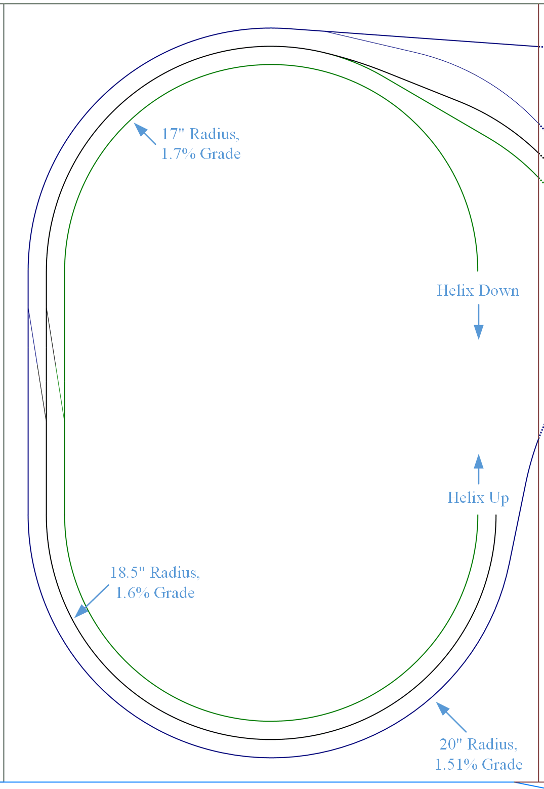
use in the rest of the layout. The inner loop will have a 17-inch minimum
radius, the middle loop will have a 18.5-inch minimum radius, and the outer
loop will have a 20-inch minimum radius. Unfortunately, the purpose of the
outer loop is often for activities other than climbing the helix, but I’ll
explain more in a future helix design post. However, radius is a major concern.
Fortunately, I do have some data to work with here. MRVP used a helix with
16.5-inch and 18.5-inch radius curves and a lap-over-lap rise of 2 3/16-inches.
(David Popp says it is only 2-inches in the videos on the layout, but he left
out the thickness of the subroadbed in his calculations.) This results in a
grade of 2.1% on the 16.5-inch radius inner loop and 1.9% on the 18.5-inch
outer loop. MR regularly runs trains of 18-22 cars with 2 engines up these
grades without issue.
 |
| Layout Main Helix Design |
This
compares well with my design. I have 17-inch to 20-inch radius curves, so my
performance should be in the same ballpark as that of Canadian Canyons.
However, because my helix is an oval instead of a circle, I get two benefits.
First of all, in order for a train to have cars on the entirety of both curved
ends of the helix, it would need to have at least 35 50’ cars, and then only 30
of the cars would be on the curved sections. Part of my grade is handled with
straight sections which will have less rolling resistance. Second, because my
helix is an oval, I get a larger lap to gain elevation due to the two 20-inch
straight sections. The result is that my helix has grades of 1.7% (inner loop),
1.6% (middle loop) and 1.51% (outer loop). Thus, I should exceed the
performance of the trains that is achieved in the Canadian Canyons loop with
the same clearances and a slightly more substantial (by 1/16-inch) subroadbed.
Based
on some experimentation, I’ve targeted a “long” unit coal train of
approximately 36 cars with the possibility of a caboose and 3 engines in the
helix. On the layout, the train would generally run with 2 additional swing
helper engines per DRGW practices. I want to do some testing of my own, but I
expect that I will be able to achieve these train lengths using this number of
locomotives based on the Canadian Canyons layout. One last point, most of the
time, I plan to use the inner loop as the downward loop, and the middle or
outer loop as the upward loop, which will further minimize the grades. Indeed,
it is on the visible layout where grades of 2%+ will be faced by the trains on
the mainline where the ruling grades will lie.
One
last note: A Happy Fourth of July to everyone reading this blog and to those
who have not yet found it. Take some time out to celebrate this country.
Remember, this is a celebration of a common dream, not of any one person, place
or thing. It is instead about America’s story, about our collective story as a
nation, and that belief that has allowed people to make sacrifices to provide others
with a chance to experience this dream. No one person is bigger than that story.
That is why the story lives on and on and on. Live the story. Pursue the dream.
Share the dream with those who are most in need of a dream. It is how the dream
lives in each of us. Never surrender your dreams.
Cameron Turner
Wednesday, July 3, 2019
Wordless (almost) Wednesday...
 |
| The Iconic Sign on Denver's Union Station. |
Cameron Turner
Tuesday, July 2, 2019
A Junction and a Helix
In the last post, I described my space and provided a conceptual benchwork configuration for my proposed layout. This post begins the description of the track plan for that layout. I often start my designs with a critical component. In this case, the component that I was most concerned about was the helix and how it would interface with the layout at Prospect Junction.
Prospect Junction in real life is an important connection. It is a double track diamond of the line into Denver Union Station from the DRGW's North Yard, and provides a connection to the BNSF and UP lines towards Wyoming and Nebraska used by Amtrak. DRGW and BNSF trains headed south for the Joint Line and Pueblo also pass by Prospect Junction. After leaving Denver Union Station, Prospect Junction is the first notable element on the ride west out of Denver.
The critical elements of the junction in my mind are as follows:
Unfortunately, the geometry of the junction is not particularly conducive to modeling as can be seen in this aerial view.
My benchwork plan allocated a rectangular area for a helix. The helix supports up to three tracks on 1.5-inch (Ntrak mainline) spacing. This is a greater spacing than I think is necessary, but it provides a little extra spacing in a critical location. The inner loop of the helix does have a 17-inch radius. However, this track is intended for downhill running and I expect that it will be acceptable. Mike Danneman's layout has an 18-inch minimum radius and performs perfectly well. Even at this radius, the grade in the helix is 1.7%. This is only slightly more demanding than the standards used by Ntrak on their Blue Line.
I was able to capture the most important elements of the junction, including the double diamonds, the joint line traffic, the ability to turn a passenger train, and the connections at the station. (The bridge over the South Platte River has not yet been added to the drawing.) Trains from the west come into the station using the routing illustrated below.
So, trains arriving from the west via the DRGW will actually cross the diamond first on the double track mainline (not prototypical) but then loop around the helix and cross the diamond in the prototypical fashion (one a single track crossing a double track) before entering the station throat. To then reverse the consist, the train would back out of the throat headed towards the BNSF/UP yards (just as in the prototype) but rather than coming around a wye as in the prototype, the train simply runs around the helix and back through the junction and into the throat. Effectively, the loop is a reverse loop which is actually going to be less problematic than a wye for the same operation.
Furthermore, trains arriving or departing via the BNSF or UP lines that lead north east out of Denver (via the 31st Street and 38th Street Yards) can also enter and exit the station throat as shown below. These trains head in and out of the staging yards located above via the helix.
Cameron Turner
 |
| Prospect Junction in Denver Colorado - by James Belmont. |
The critical elements of the junction in my mind are as follows:
- The double diamonds crossing the BNSF main to the Joint Line;
- The bridge over the South Platte River;
- The connection to the BNSF wye for turning and cleaning passenger trains at Denver Union Station;
- Connections to the DRGW line west, the BNSF and the UP lines headed north and east;
- Proximity to the Joint Line traffic headed south; and
- Proximity to the BNSF engine facility.
Unfortunately, the geometry of the junction is not particularly conducive to modeling as can be seen in this aerial view.
 |
| Aerial View of Prospect Junction. |
My benchwork plan allocated a rectangular area for a helix. The helix supports up to three tracks on 1.5-inch (Ntrak mainline) spacing. This is a greater spacing than I think is necessary, but it provides a little extra spacing in a critical location. The inner loop of the helix does have a 17-inch radius. However, this track is intended for downhill running and I expect that it will be acceptable. Mike Danneman's layout has an 18-inch minimum radius and performs perfectly well. Even at this radius, the grade in the helix is 1.7%. This is only slightly more demanding than the standards used by Ntrak on their Blue Line.
 |
| Track Plan for Prospect Junction and the Helix. |
 |
| Routing for Trains arriving from the West (DRGW). |
 |
| Reversing a Passenger Consist. |
 |
| Passenger Train Connections to Staging. |
The plan for Prospect Junction is not perfect (or perfectly prototypical)
but it will function effectively both operationally and in terms of faithfully telling
the story of a train leaving the station to travel Thru the Rockies...Not
Around Them.
Cameron Turner
Subscribe to:
Posts (Atom)