With a subject identified, my next step is to consider the footprint available for the layout. That footprint is related to the desired architecture of the layout. In this case, I have selected that as well. In my earlier plan, I began to play with a concept I call a double helix layout, which is two nested helices, one climbing up and the other climbing back down. One or both could in theory be sceniced, but it allows the layout to climb to a summit and then descend the other side. For this layout, I plan on scenicing one helix, while hiding the other one, in large part due to the available space for the layout.

The room available for the layout is 11' wide, and 27'-9.5" long. The lower side of the room (in the drawing above is a built in bookcase that separates the room from an adjacent family room/crew lounge, which is not available for the layout. The upper wall is currently occupied by a set of 3 double door closets, and a built in sink. Within the upper right hand closet is an entrance to a crawl space which has to be maintained. The right wall also has the intake for the basement AC/heating system. The left wall has a door which exits into the garage. Located on the opposite side of the wall in the garage is a utility sink and a washing machine, so that left wall is full of plumbing.
The closets and sink can be relocated - however, the closets represent a significant amount of storage for the house. However, at 32" deep, they could be reduced in depth if not eliminated. Similarly, the sink could be relocated, and consolidated with the sink in the garage - which I would also like to get out of the garage, along with the washing machine (if it cannot be eliminated altogether as it is not the primary washer in the house). Since the left wall contains plumbing, it makes sense to locate these elements on the left wall. Doing this, and replacing the closets with 16" depth shelves, results in the room plan below.

I've also extended the shelves over the new sink and washing machine. Allocating between 30" and 36" for aisles around the layout produces a possible footprint that is about 20'-9" long and between 44" and 56" wide.
My next concern is to determine how the hidden helix will affect the necessary width of the layout. Because the down helix will be a substantial run and will need to handle bidirectional traffic, it will need to be double tracked. In addition, there will need to be a third track in the helix, at least from the lowest staging level to the bottom of the visible portion of the layout. So, the helix is at least three tracks wide. Since two tracks have to run from the top of the helix to the bottom, those two will need to be the innermost tracks. Based on the Model Railroader Canadian Canyons layout, which used an N-scale Helix with a radii of 16.5" and 18.5", I plan to use an inner radius of 17" and to make this track the default downhill track. Based on my experience in Ntrak, I plan to use 1.5" track spacing in the helix, thus, this makes the radii of the helix 17" - 18.5" - 20". I'll add 2" to the inside and outside openings in the helix, so the inner access space of the helix will be a 15" radius curve, and the outer edge of the helix at a 22" radius. This makes the helix 44" wide, which with the scene wrapping around the outside of the helix, would imply a scene of no more than 6" deep and probably less. Perhaps the aisles should be narrowed a little more around this blob so as to allow for a slightly deeper scene?
Of course, another alternative is to locate the top-to-bottom helix at one end of the layout, and the shorter helix between staging and the lower end at the other end. This would mean that the visible portion of the layout would have an odd number of long runs. In my prior plan, I had six long runs, which equated to the following scenes:
- Minturn;
- Lower Eagle Canyon;
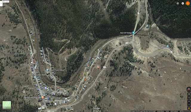
- Belden-Red Cliff;
- Camp Hale;
- Dean-Mitchell-West Tennessee Pass; and
- East Tennessee Pass.
Having an extra side is interesting, as it would allow me to insert a bit more of a run between Red Cliff and Camp Hale, as well as spacing Dean and Mitchell a bit further apart. But would that also work vertically? More specifically, can I make the grades work with that concept? I see a couple of potential advantages. First, the helix component drops from 44" side to 41" wide, and I could have 7.5" deep scenes around the helix without impinging on the aisles at all. Second, the length of the layout could be used to help make the entrance to the staging yard from the lower end of the layout be more visible by reducing the run in the helix. Third, as mentioned before - spacing is key. The railroad disappears between Red Cliff and Camp Hale and there was time between a train passing at Dean to get to Mitchell, so it would be nice to space those scenes more appropriately. So, at this point, I want to look at this at least as a promising concept.with this concept, these would be the following scenes for the long sides of the layout:
- Minturn;
- Lower Eagle Canyon;
- Belden-Red Cliff;
- Silver Gulch;
- Camp Hale-Dean;
- Mitchell-West Tennessee Pass; and
- East Tennessee Pass.
Just as a thought, if I could get an eighth side added, I would actually add a bit of the Avon/Eagle area in to the west of Minturn to add some additional switching, but because I would like to have Minturn be fairly level, I do not see exactly how I would do that, but I can keep that in mind. The tough part of this plan is that it places East Tennessee Pass above Pando siding (at Camp Hale), Camp Hale above Belden and Red Cliff and those above Minturn, all on one side of the layout. On the other side of the layout is the Mitchell-West Tennessee Pass above Silver Gulch which is above the Lower Eagle Canyon. All of which are scenery elements. Thus all the operational elements are on one side of the layout and all of the spacing elements are on the other side. This is not going to be good for the traffic of the operators, who are all going to be busy adding helpers in Minturn, switching at Belden and Red Cliff, passing in Pando, and taking helpers off at East Tennessee Pass. No, that idea is not a good one.
So, Silver Gulch needs to be dropped off as a full side. Instead, what if I placed Avon/Eagle in to the West of Minturn. This would lead to the following scenes:
- Avon/Eagle;
- Minturn;
- Lower Eagle Canyon;
- Belden-Red Cliff;
- Camp Hale-Dean;
- Mitchell-West Tennessee Pass; and
- East Tennessee Pass.
This works much better I think. While Belden-Red Cliff are still located over Minturn, they are at least located more towards the ends of the layout, and should be able to work with the Minturn yard master to share space. Avon/Eagle, Pando Siding (again at Camp Hale) and East Tennessee Pass are all above each other, but it is hard to imaging that all three will be busy at once, so this is at least a better balance of aisle traffic. So, that is the plan at the moment - at least assuming that I do want to separate the helices. And with that in mind, that led me to develop an initial proposed layout boundary.

In defining the shape, I did narrow the aisle on the left to 27", but it immediately gets wider past the corner of the sink, all other aisles only neck down to 30" right now. This means that I have some narrow scenes, at 7.5" depth, but those can likely be deepened by narrowing the aisles further for short stretches. I currently have the top-to-bottom helix on the right side, and as the layout progresses upward in a clockwise fashion, this places East Tennessee pass on the upper side of the layout. This too works, as any expansion would likely extend over onto the shelves (first) and would create a walk under area in the upper right hand corner. Minturn Yard is thus on the lower side of the layout, and I widened the aisle and benchwork to accommodate yard operations. The lower helix on the left would climb clockwise, while the top-to-bottom helix could climb in either direction. That will need to be determined. But, that is my thought process, at least to this point.