Showing posts with label Clay. Show all posts

Tuesday, November 5, 2019

The Turning Point – Part 5: Rocky, the Big 10 and Clay Revised

The original configuration of Rocky Siding, the Big 10 Curves and Clay were close, but not quite satisfactory in the prior plan. These features were placed along the top wall in the original plan, in a configuration like this.

Original Layout Plan for Rocky-Big 10-Clay LDEs.
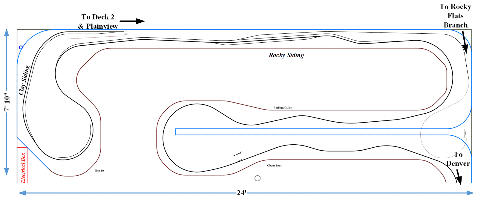
The new plan is a very similar footprint. However, with the changes in the shape of the peninsulas, the lobe with the Big 10 Curves could be extended, and a small bulge was introduced along the long wall which corresponds to the gap between the two peninsulas in the room. I relocated Rocky a little to the right, and Clay further around the Big 10 curves. This now puts nearly 17 feet of track between the west switch of Rocky and the east switch of Clay, which should be longer than my longest train. So, that problem was solved. This also allowed for a little more elevation to be gained between the two decks. Railhead to railhead clearance is nearly 7 inches, and the upper deck will be located more to the rear of the layout, while I was able to use the bump out to push the lower deck closer to the front. So, even with a relatively narrow perspective on the lower deck, the effect should not be like looking into a deep cave. Generally, I think that the configuration works much better.

Revised Layout Plan for the Rocky-Big 10-Clay LDEs.
I particularly think that the representation of the Big 10 curves is better. Granted, the west switch of Rocky is not in the Little 10 curve as it is properly, and the east switch of Rocky now falls to the east of the Highway 93 bridge, rather than to the west, but I think both are reasonable compromises. I could look at relocating the Highway 93 bridge closer to the entrance to the Rocky Flats helix, but I am not sure I want to do that either at this point. The next question is really how will this new configuration affect the second deck, and is the deck separation really improved? Right now, the point where the junction switch is for the Rocky Flats Branch is at 12.25" above the reference point ( which is Prospect Junction at 0"), and the west switch of Clay is at 19". Considering the deck to deck effective distances will need to be done with the rest of the second deck in place.

25 Days, 25 Posts to go!

Cameron Turner

Wednesday, September 18, 2019

Wordless Wednesday

Clay Siding with Amtrak #42 leading the California Zephyr West. Photo by John Crisanti.
Cameron Turner

Sunday, September 8, 2019

The Turning Point Part 3: Rocky, the Big 10 and Clay

To complete the design of the Layout Design Complex (LDC) that is formed by the layout design elements of the exit from Barbara Gulch under the US-36 bridge, the siding and junction of Rocky, the Big 10 Curves, and finally the siding of Clay, there needs to be an analysis of the grades to determine if they are effective in providing the transition between layout decks. To read the previous entries about the LDC (Part 1) and the design of the LDC (Part 2) see those blog entries.

Not knowing what the elevation of my low point of the layout will be relative to the floor, I planned this layout with a low point set at Prospect Junction near the crossing of the South Platte River. The line climbed around through North Yard, achieving a climb of +2.5" by the time that the main line reached Utah Junction. The climb continues, just as in the prototype on 1% or less grades through C&S Junction, Arvada, Leyden and Barbara Gulch. By the time the main line reaches the bridge carrying US-36 over the railroad, and enters Rocky, the main line has climbed to +8.5" over the reference point at Prospect Junction.

Main line climb through the Rocky-Big 10-Clay LDC. All elevations are relative to the height of Prospect Junction.
 I made the decision to provide a flat spot in Rocky up until the point where the Rocky Flats branch joins at Rocky Junction. From here, I have the main line climb, slowly at first, but with the grade growing. The prototype grade becomes 2%, but I found that I needed a little stiffer grade to achieve the desired elevation climb. In the end, I settled on 2.5%, with the turnouts not included, so the actual grades will be a little less.  By the time the main line reaches the west end of Rocky siding, the main line has climbed to +9.6". The main climbs another inch by the time the Big 10 windbreak is reached, and to +11.63" by the time that the wind break ends. The line reaches +12" by the time that Clay siding starts, a climb of +3.5" from where the line entered Rocky. The climb continues through Clay, reaching +14.75" by the west turnout.

At this point, my vertical clearance is 5.75" rail head to rail head. In N-scale, minimum clearance as specified by the NMRA is 1.72", and I treat it as 2". So, at this point, I do have about 4" of clearance from the top of the lower train, to the rail head of the upper main line. If I subtract out a minimum of 2" for a thickness of the bench work, that leaves only 2" which is not enough. Fortunately, I can keep the mainlines from crossing each other for a while, allowing me to climb to an elevation of +16.5" almost directly above Rocky Junction (located at an elevation of +8.5"), which allows me to double the clearance between the top of the equipment on the lower deck and the bottom of the upper deck. Is this enough? Time for a mock-up to see how it looks.

Mockup of the two levels with an 8" rail head to rail head height and a 2 inch bench work thickness.
I used an adjustable bookshelf to create a simple mockup of the bench work where the two levels overlap. The plan has the depth of the bench work at this region set as 12 inches, and, and my bookshelf is only 11", but it gives you a good idea. With a few clamps to hold a strip of wood to simulate the full thickness of the bench work, and a few binder clips to place a couple of led strip lights under the bench work to provide light, I proceeded to arrange a couple of pieces of Kato Unitrack and a couple of 60' Atlas N-scale passenger cars I had handy into the scene. My conclusions:

  1. Without the led lights, the lower deck is clearly too dark. And the viewing height versus eye level will be crucial. The shelves I used were lower than the likely layout height at this transition, but there is clearly a relationship.
  2. Surprisingly, the height is workable. You can get your hand in to fix a derailed car if necessary, provided that the shelves are not too deep. The scene is also helped by not having foreground structures that reach the bottom of the upper deck.
  3. It is also apparent that the lower level works best if the scenery intended to be viewed during operation is closer to the front. This will also help the lighting needs of the layout.

Another view from a higher viewpoint and with the lower level track about 6 inches back into the scene.

    All in all, I am pleasantly surprised that this is enough clearance, at least for a brief transition if the scenery is carefully planned. However, I would in general prefer to get a deck separation (track to bottom of the lower deck) of closer to 12-14" in general. I will need to do some further analysis to help determine exactly how to manage this scene.

    Another design concern is as to whether the Big 10 Curve is large enough to feel realistically "large" versus a train. A typical coal train may be about 13.5' long. Laying out such a train through the Big 10 Curve shows the following.
    A 13.5' Coal train (In Orange) through the Big 10.
    As the train enters Clay, its tail would still be in Rocky. However, by the time the train clears Rocky, its head would be passing by it on the siding above in Clay. There should be nearly 1.8 miles between the sidings and a Moffat Coal train would be approximately 1.3 miles long. So, the sidings are a little close. But does it give the right feel? I think it is pretty good, but if possible, a little more length would be good to include between the sidings.

    My conclusion - the plan is nominally workable, but should be revisited. The plan can continue onto the second deck, but further consideration may be necessary to see if some additional improvement can be achieved to increase the deck separation, manage the viewing height, and lengthen the distance between Rocky and Clay. While 1.8 miles (about 59') is probably impractical, perhaps something greater than 13.5' should be targeted.

    Cameron Turner


    Friday, September 6, 2019

    The Turning Point Part 2: Rocky, the Big 10 and Clay

    So, given all the information in Part 1 of our discussion of the design of the Rocky, Big 10 and Clay Layout Design Complex, what can we make out of it to form a design? Fortunately, all the twists and turns of the line exiting Barbara Gulch, Rocky, the Big 10 and Clay really do resemble a toy train layout which twists and turns back on itself, climbing steep grades. As this part of the layout is intended to transition from one deck to a second deck, this is to my advantage, and indeed, since the first days that I started considering a layout of this area, I fell on the idea of using this set of layout design elements, the collection of which I am referring to as a Layout Design Complex (LDC), as a deck transition point. As part of my effort to design the LDC, I began with a full scale drawing of the area.

    A Full Sized N Scale Model of the Big 10 Layout Design Complex.
    Obviously, at a massive 19' by 62', there is little hope of modeling the complex in full scale. But here I can note a few things. First, the 10-degree curves work out to be a 43 inch radius in N-scale, and I plan to model this with a 19.375" radius or 45% of full scale. Second, my target train length is also about 33% of full size, so, a 1/3rd scale model might be more appropriate. This reduces the size to about 10' by 21'. So, now I fit within my room. With a little twisting of the layout, I could end up with a more suitable configuration that looks a bit more like the drawing below.

    Squeezing and twisting the mainline, while reducing the size to about 1/3rd of full-size, yields a much more manageable plan. The biggest difference is that the main line to Plainview will twist onto the second deck above Rocky, transitioning somewhere near the northern part of the Little 10 curve.
    This plan is now about 8' by 21', and with a little more work, begins to resemble the configuration that I have room for in the bench work. This in turn led to the following plan.

    Layout Plan for the Rocky-Big 10-Clay LDC.
    The resulting plan generally resembles the actual geography of the area. Rocky Siding ends up with a 17' siding, and Clay ends up with an 8' siding. Just as in the prototype, Rocky is a fairly long siding, and Clay will be a short siding, generally useful only for passenger trains. The Rocky Flats branch enters the main line at Rocky, connected with a 4% grade to enable a grade crossing of US-93 just beyond the bridge that carries the highway over the mainline. However, shortly after this crossing, I will need to arrange for the line to disappear from the scene so that it can connect to a helix leading to either the modeled branch or a staging yard for the branch.

    There is also one challenging room constraint. As can be seen on the lower left hand corner, there is the electrical boxes for the house (in red) that will intrude on the Big 10 scene. Generally, I think this configuration is manageable. I can certainly open the boxes and manipulate the fuses in the space available. Should complete access be needed to the boxes, I plan to design the Big 10 to ride on a rolling table. The piece of bench work between the dotted lines will be removable, and will include the deck over deck transition, so that the remaining table with the Big 10 curve on it, can be rolled away from the wall. This should allow access to the electrical fuse boxes.

    Conceptually, in 2D, the plan appears viable, but now the question becomes "Will it work in 3D?" In other words, can I achieve a reasonable deck over deck separation to make the scene work? And what is a reasonable deck over deck separation anyways? So finally, the estimation of the grades necessary becomes important.

    Cameron Turner


    Tuesday, September 3, 2019

    The Turning Point – Part 1: Rocky, the Big 10 and Clay

    Everything up to this point has been but a prelude to the DRGW assault on the Rockies. This assault begins with the siding of Rocky (MP 18.0) at the foot of the Big 10 Curves. Rocky is a 7330 foot siding with a house track and the junction with the Rocky Flats branch. The Rocky Flats branch is the last significant industrial work east of the Moffat Tunnel. On the main line, to the west of Rocky, lies the Big 10 Curves, a series of 10-degree railroad curves (radius of about 574 feet or 43 inches in N-scale)  along the inside of a natural amphitheater and then along the outside of a bluff that allows the DRGW to gain critical elevation for its assault of the front range of the Rockies. The line which up to this point was nominally headed west, swings towards the north, then 270 degrees back through the south to the east, and then another 180 degrees to the west, before another 90 degree swing to bring it to the north, and into the 5780 foot siding of Clay (MP 21.2).

    Looking over the Big 10 Curves facing southeast. That is Denver in the distance, with Clay siding in the foreground. Rocky siding is just to the left of the picture on the lower level of the loops. Photo by David Langdon.

    Rocky Siding - the Big 10 Curves - Clay Siding from Google Maps.
    Looking at the area on Google Maps gives another view. The main line enters from Barbara Gulch and crosses under the US Highway 36, running between Golden and Boulder, and enters Rocky Siding.

    A train led by UP6773 leaves Rocky east bound for Barbara Gulch. The snow cleared out of the upper and lower loops forming the Big 10 can be seen in the background. February 8, 2012 by Cameron Turner.


    UP5715 leads a train under the US-36 bridge into Rocky Siding, June 4, 2015 by Cameron Turner.
    Rocky extends into the natural amphitheater, providing a significant siding for trains to pass, as well as serving the junction to the Rocky Flats Branch. That branch leaves Rocky on a 4% grade to climb to a grade crossing across US-36, and then CO Highway 72, as it heads north along US-36. Exploring the area with Google Earth in 3D yields a number of interesting views.

    Google Earth View looking south west. The Rocky Flats branch exits to the lower right hand side of the picture, while the mainline to Barbara Gulch exits the lower left. The mainline headed west exits along the upper right hand side of the image.

    Another Google Earth Image looking north. In this view, Barbara Gulch exits the lower right hand side, and the upper Big 10 curve is on the left side of the image.
    Wrapping along the lower bowl, also called the Little 10 Curve, the mainline climbs on a 2% grade before reversing course to climb around the outside of a bluff that forms the Big 10 Curve. Trains on this bluff are protected from the high winds that can exist in the area by a set of abandoned hopper cars welded to a set of rails on the inside of the curve. Nature has overgrown many of these cars.

    Installed in  November or December of 1971, a string of hopper cars filled with dirt made a suitable windbreak to protect cars from high winds in the area. Photo by Ray Kenley.
    The hopper cars placed in 1971 have become the basis for a number of trees and bushes to grow in the winds. Nonetheless, the winds affect their growth as can be seen by how they lean towards the cars. Photographer Unknown.
    Even the dirt in the cars has proven to be a suitable place for grasses and weeds to grow. Photo by Loco Steve.
    Google Earth view of the windbreak. Here, the hopper cars are vague rectangles of foliage.
    More details about the windbreak can be found here. Past the windbreak, the line turns and enters Clay siding. Originally named Fireclay for the clay mined in the area and used to make bricks, the siding name was shortened to Clay. Today, it has been renamed Eisele for a UP official. The siding is short, and thus rarely used. Furthermore, the siding itself is on "soft" ground, and hence its use is restricted to light trains. I've only seen it used for passenger trains to pass freight trains. All in all, each of these three elements are a fundamental component to modeling the area.

    Cameron Turner