Showing posts with label Canadian Canyons. Show all posts

Thursday, July 4, 2019

Adding a Twist…

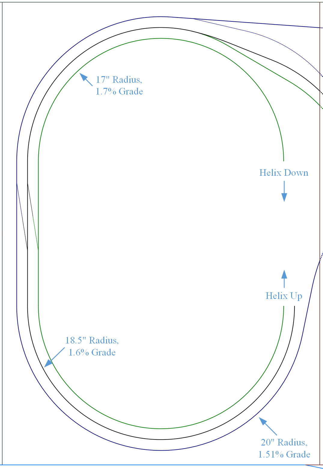
The helix is a critical element to the plan for the layout, so its design was one of the driving factors in the configuration of the layout. The purpose of the helix is two-fold. First, it is intended to connect the various “exits” from the modeled layout to the various staging yards. Second, because I desire to make the layout as close to self-staging as possible (so as to minimize the effort required between operation sessions), the helix provides a continuous loop option between the ends of the layout. Because of the grade of the layout and its multiple deck nature, this means that the helix could become quite a bottleneck, which has led me to double track the helix for most of its length.

Helix Diagram.

And its length will likely be substantial. Exiting the layout near Prospect Junction, I am predicting that the upper entrance of the layout (modeling somewhere west of Tabernash, Colorado if all goes well) will be around 37.5-inches above Prospect Junction. With a target climb per lap of the helix of 2.5-inches, this means that there will be about 15 laps in the helix. That is a lot of track, and it will need to be pretty much bullet proof.

So, where do these numbers come from? Well, let’s take a look at how I came up with 2.5” for a lap of the helix. I plan on laminating the helix sub-roadbed together using two layers of 1/8-inch wood with any joints staggered. This gives me a 1/4-inch thickness. Add to that an 1/8-inch thick cork roadbed, and another 1/8-inch thickness for the track and that gets me to a total of ½-inch thickness. NMRA Recommended Practices suggest that a in N-scale, 1 23/32-inch is necessary over the railheads. I round this up to 2-inches to give me a little wiggle room. And there we go, 2.5-inches. This also similar to the MRVPCanadian Canyons layout railhead-railhead height in their helix. I’ve previously commented on that layout and its inspirations to my own efforts. It is well worth the cost of an MRVP subscription to watch this excellent series.

Model Railroaders Canadian Canyons Layout showing their completed helix.
My design has as many as 3 loops of track in the helix. The loops will have 1.5-inch spacing, consistent with Ntrak standards, and more generous than I am going to use in the rest of the layout. The inner loop will have a 17-inch minimum radius, the middle loop will have a 18.5-inch minimum radius, and the outer loop will have a 20-inch minimum radius. Unfortunately, the purpose of the outer loop is often for activities other than climbing the helix, but I’ll explain more in a future helix design post. However, radius is a major concern. Fortunately, I do have some data to work with here. MRVP used a helix with 16.5-inch and 18.5-inch radius curves and a lap-over-lap rise of 2 3/16-inches. (David Popp says it is only 2-inches in the videos on the layout, but he left out the thickness of the subroadbed in his calculations.) This results in a grade of 2.1% on the 16.5-inch radius inner loop and 1.9% on the 18.5-inch outer loop. MR regularly runs trains of 18-22 cars with 2 engines up these grades without issue.
Layout Main Helix Design
This compares well with my design. I have 17-inch to 20-inch radius curves, so my performance should be in the same ballpark as that of Canadian Canyons. However, because my helix is an oval instead of a circle, I get two benefits. First of all, in order for a train to have cars on the entirety of both curved ends of the helix, it would need to have at least 35 50’ cars, and then only 30 of the cars would be on the curved sections. Part of my grade is handled with straight sections which will have less rolling resistance. Second, because my helix is an oval, I get a larger lap to gain elevation due to the two 20-inch straight sections. The result is that my helix has grades of 1.7% (inner loop), 1.6% (middle loop) and 1.51% (outer loop). Thus, I should exceed the performance of the trains that is achieved in the Canadian Canyons loop with the same clearances and a slightly more substantial (by 1/16-inch) subroadbed.


Based on some experimentation, I’ve targeted a “long” unit coal train of approximately 36 cars with the possibility of a caboose and 3 engines in the helix. On the layout, the train would generally run with 2 additional swing helper engines per DRGW practices. I want to do some testing of my own, but I expect that I will be able to achieve these train lengths using this number of locomotives based on the Canadian Canyons layout. One last point, most of the time, I plan to use the inner loop as the downward loop, and the middle or outer loop as the upward loop, which will further minimize the grades. Indeed, it is on the visible layout where grades of 2%+ will be faced by the trains on the mainline where the ruling grades will lie.

One last note: A Happy Fourth of July to everyone reading this blog and to those who have not yet found it. Take some time out to celebrate this country. Remember, this is a celebration of a common dream, not of any one person, place or thing. It is instead about America’s story, about our collective story as a nation, and that belief that has allowed people to make sacrifices to provide others with a chance to experience this dream. No one person is bigger than that story. That is why the story lives on and on and on. Live the story. Pursue the dream. Share the dream with those who are most in need of a dream. It is how the dream lives in each of us. Never surrender your dreams.

Cameron Turner


Friday, June 16, 2017

Considering a Concept

Well, with all the other items discussed, I have been doodling in the background. Having the train space in CAD is nice, as it allows a number of quick visualizations. One of the first drawings that I looked at is below.

Usable Space
Each of these lines represents the remaining space given aisles of various widths. Clearly, as long as the closets and sink (top of the picture) are in place, I am fairly limited. Access along the right side is a necessity, and the left side must deal with the door to the garage. About the only useable wall space at the moment is in the upper left hand corner - if the door to the garage does not have to open all the way - which it does not.


So, this is part of the fun. It is a challenge. Well, I have been following the Canadian Canyons Series on MR Video Plus. This is the most excited I have been about a project layout in Model Railroader in decades. I really like how the layout uses a helix to connect to a staging yard to form the loop. And so a concept may be born.

Looking at my space, and sketching out where the benchwork could go, I arrived at the following conceptual benchwork configuration.

Conceptual Benchwork
There is room for a helix on the left, and the trains could run around the layout and be followed by a crew all the way around the room. In only a few spots, do we have some sub-24" pinch points, and often we are wider. As a test layout, this concept has potential. It has the shelf style I am anticipating, yet could easily support full length trains. A cleaner benchwork drawing without the aisle potentials is shown below.

Dimensioned Benchwork
The layout is broken into 7 sections - each of which will fit out of the sliding door in the basement. Six sections are sceniced - and the seventh would be the helix. The layout may even be somewhat portable in case I need to move, or want to take it to a show.

So, this benchwork was not created solely by the space, but with a concept in mind. That concept is drawn from the Canadian Canyons Layout. I've drawn up a rough plan of the Canadian Canyons Layout on my own.


So, the tracks run through staging, climb the helix on the upper left hand side and then run through the sceniced layout, before descending the helix and returning to staging. It is a giant loop, but it sparked an idea. What if, my layout did much the same thing, climbed out of staging, ran around the perimeter of the layout and the returned to staging by descending the helix. A little quick math suggested that my visible run could be about 52 feet. In N-scale, that is about 1.6 miles. Since many of the places I am interested in modeling are centered around a grade, so, what I used that stretch to model the grade. Running a few quick calculations led to the following:

...a 1% grade would climb about 6.3 inches.
...a 2% grade would climb about 12.6 inches (think Moffat Line/Craig Branch).
...a 2.2% grade would climb about 13.9 inches (think Soldier Summit).
...a 3% grade would climb about 18.9 inches (think Tennessee Pass).

These are very interesting numbers. Playing with a bookshelf, I am convinced that in N scale, you need to have about 10 inches between the scenery base on the lower deck, and the underside of the upper deck. If you can get 12 inches, all the better, and then you need 2-4 inches for the deck structure. In other words, 12-16 inches of deck separation works for me - particularly if you are talking about 10-16 inch deep scenes. With this in mind, you could almost circle the available benchwork and climb to the next deck in the process.

So, what if the layout climbed out of the helix from staging, climbed around deck 1 to deck 2, circled around while still climbing on deck 2, and then descended the helix. Heck, you might be able to do it 3 or even 4 times. Interesting!

So, I have a concept for a layout that would start in staging, climb out of staging to a first deck, and then tackle a grade to the summit, before descending the helix back to staging. I've had similar ideas in the past and so I adopted a term for it - the double helix layout. This could be a chance to try it out.

Following some quick math, the footprint of the layout is 78.36 square feet, and I think I can more or less have staging + 3 decks, so a total of 313.5 square feet of layout, with a visible main line run of about 156 feet or almost 5 scale miles. Granted, the helix connecting the visible top with the staging level would be massive - but that too could be used for elephant staging (trains nose to tail) so you would not "see" the delay climbing the helix, and going down the helix could be automated or managed by the staging hostler. But a 5 scale mile helper grade, that could be a site to be seen.

Okay, so back to the concepts - Focusing on standard gauge for a minute - the Moffat would be the toughest, the grade is at the low end, which would lead to minimal clearances throughout, and if you had some flatter spots at towns, the climb distance it not there. Furthermore, some of the signature features, such as the Big 10 curves, don't work well at all. The Craig Branch has similar issues with some of the scenes (Crater loops), but perhaps a piece of it could be achieved. Soldier Summit does a bit better, it is worth considering, and given that there are few real towns on the eastern side - maybe. The western side has Gilluly Loops - that won't fit well at all. That leads us to Tennessee Pass, with a western side with 3% grades, virtually all a helper district, only a few sidings, and even where it levels out, we are often still talking about 1-2% grades. Promising.

So, it sounds like I have some concepts to draw up, and let us see how they look. Then there are some other options if I look at the Narrow Gauge options too. But I'm going to start with the standard gauge ideas and see how they look.