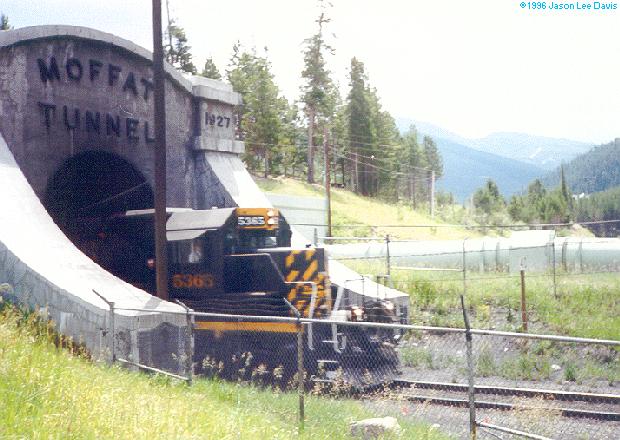
One approach would be to not model it at all. This is the Mike Danneman solution in his layout, where the Moffat Tunnel becomes the entrance to a helix to the staging yard. I considered this solution. However, I really wanted to include Winter Park and either Fraser or Tabernash (if not both) so that I could model the end of the run of the Ski Train. So, I wanted to model the West Portal of the Moffat Tunnel as well.
Another approach would be to use the room, perhaps wrapping the tunnel around the room on a narrow shelf. I considered this, but decided that I could do better. The third option I considered was to use a helix within a helix to provide length while first climbing, and then descending within the ascending helix. Thus, I could have the summit inside the tunnel, while making the elevation difference between the east and west portals only a few inches.
Eastern Moffat Tunnel Plan.
In the plan, the east portal leads to the outside of the helix. The track climbs, spiraling in until it reaches an elevation of 54.25 inches, 4 inches above the east portal entrance. The track levels off for 135 degrees, a length of 46 inches. Then, the track begins to descend on an inner helix. After almost three complete laps, the track emerges at the West Portal of the Moffat Tunnel.
Western Moffat Tunnel Plan. One intermediate lap between the eastern and western parts of the tunnel is not shown in the plans.
The result is a tunnel that ascends four inches, then descends 7.375 inches for a cumulative descent of 3.375 inches. The resulting tunnel is about 50.5 feet long or about 1.5 scale miles. The model representation of the tunnel is about a quarter of the prototype tunnel length. The summit of the tunnel comes to within about 8-9 inches of the ceiling. While I could add additional laps to the helix to climb higher before descending again and lengthen the tunnel, I think this length is reasonably proportional to the other tunnels in the layout. Operating such a long tunnel will be a little discomforting for many engineers, so the helix as is will need to be signaled to inform the engineers of the continuing progress of the trains through the tunnel. Such sensor systems are not unusual in similar applications.
The last siding on the east side of the climb to the Moffat Tunnel lies just east of the eastern portal and is called East Portal. The siding is 5750 feet long, slightly longer than Tolland. One of the primary purposes of the siding is to queue trains waiting for the tunnel to ventilate. The 6.2 mile long Moffat Tunnel was built between 1924 and 1928 and also includes a second bore used to bring water from the western slope to the eastern slope. This water is fed into South Boulder Creek at the tunnel.
I was able to use a combination of satellite images of the East Portal complex, and a set of plans published in the 1980s to create a scale plan of the site and the different structures. Based on the space available (the area above North Yard) I did need to consolidate the structures a little bit, but the buildings are full size. As a signature element of the layout, I want this facility to be an accurate model of the real location.
I recently found a video of a drone at the Moffat Tunnel which also gives some additional views and details.
With such a long tunnel, ventilation is a necessary consideration, particularly with the summit inside the tunnel. Both east bound and west bound trains have to climb while in the tunnel, and as can be seen by how dirty engines got on the Moffat Line, a ventilation system had to be installed in the tunnel. The door opens when an east bound train gets within 1500 feet of the tunnel portal and closes after the train departs the tunnel. The tunnel doors also close about 40 seconds after a westbound train finishes entering the tunnel. The fans ventilate the tunnel for approximately 20-25 minutes after the portal closes. It takes a train approximately 9 minutes 30 seconds to traverse the tunnel. The doors seem to take 10-20 seconds to close. I plan to model the operation of the door.
The Tunnel is not the only thing at East Portal. There is a wye that used to lead to the line over Rollins pass, and a number of structures, including a two stall metal train shed. I am not exactly sure what the purpose of the train shed is, but suspect that it is used to store tunnel maintenance and snow equipment.
View at East Portal looking east. The train shed and a storage shed are to the left of the engine. Photo by Jim Carr.
I tried to capture most of these features in the track plan for East Portal. The siding is 111 inches long, a little longer than Tolland.
East Portal Track Plan.
In addition to the siding, I have included the wye, bringing the third leg of the wye out over the aisle for North Yard. This should work for most operators, as the benchwork should be approximately 77" above the floor, so most people will walk right under the wye. Given the elevation, I tried to keep the track accessible, and to the front of the benchwork. However, it will take a step stool to work East Portal. I've been able to include many of the structures, including the tunnel and the associated ventilation system. As the main line enters the tunnel, like the prototype, it begins to climb.
The Moffat is known for the tunnel district. Between Denver and the Moffat Tunnel, a distance of 50 miles by rail, there are 28 tunnels. These are clustered in a span of 17.3 miles, starting with Tunnel 1 (MP 23.2) and ending with Tunnel 30 (MP 40.5). (Note that Tunnel 9 and Tunnel 28 no longer exist.) This series of tunnels and the regions through which they take the Rio Grande is one of the major reasons for my interest in the line.
Caboose 01460 rolls by while a gaggle of SD45s pulls the train into
Tunnel 1 on the far side of Coal Creek Canyon. Photograph by Chuck Conway.
The tunnels at the ends of the district are orphans. They
are different from the rest of their siblings. Tunnel 1 allows the main line to
withdraw from its first encounter with the front range and retreat to climb
along the Flatirons that make up this barrier. Indeed, there are 2 miles
between Tunnel 1 and Tunnel 2. Furthermore, one could also argue that it is a
full 3.5 miles before the railroad once again tries to thrust its way into the
mountains like it does in Coal Creek Canyon. Tunnel 1 is a prologue to what is
coming, and Tunnel 30 is a reminder of what the railroad has gone through to
get there.
Tunnel 1 is 299 feet
long, or 22 inches in N-scale. Indeed, it could be modeled in full scale at
that size. However, as I worked on developing track plans to model the tunnel
district, I found that while some tunnels could be modeled at scale (Tunnel 29
is only 78 feet long), others would be challenging (Tunnel 17 is 1730 feet
long). Early on, I adopted a goal to model the tunnels using a formula so that
the shortest tunnels would be full scale, while the longest tunnels would be shortened
to something more reasonable. Using this formula, I established the following
goals for modeling each tunnel, as shown below.
Table of the actual versus target design lengths for the layout tunnels.
I am pleased to note that the median (0.84) and average (0.83)
compression ratios are very similar. Furthermore, the target tunnel lengths all
maintain the rank ordering of tunnels in terms of their length. Several tunnels
(4, 7, 22 and 29) have little or no compression, while the longest tunnels (10,
17, and 23) all are much more palatable in terms of length. For instance,
tunnel 10 would be 117.9” long at full scale, but its target design length is
now 75.46”. At a little more than 6 feet long, that is still a long tunnel, but
many trains will still be long enough to be visible while in the tunnel. If
modeled to full scale, that would not be the case. Yet, a six foot tunnel still
garners the feel of an immense tunnel.
Tunnel 1 is the first tunnel to transverse a sand and pebble
conglomerate that forms the backbone of the flatirons. The flatirons are up thrust
sedimentary slabs that form a picturesque backdrop to Boulder, Colorado. The railroad
east and west portals are both concrete with sprayed concrete and gunite added
in between to maintain the stability of the tunnel. The exterior of the rocky
outcrop through which the tunnel passes is dotted with ponderosa pine trees. Based
on the target length for Tunnel 1, the model should be approximately 20 inches
in length, about 89% of the full-scale tunnel length but still substantial.
Plan for the Tunnel 1 area.
Just to the railroad west of Tunnel 1 is a grassy area where the mainline curves around as it prepares to swing around to the north and enter a flat spot known as Plainview. I positioned Tunnel 1 to allow for this curve while achieving the target design length of 20" which works out to be about 267 scale feet. This is very close to the target length. This last stretch of main line also brings to an end the steepest climb on the railroad. Just as on the real thing, the main line grade moderates at Plainview as the line enters Plain Siding, but more on the design of Plainview in another post.


 Posts
Posts