Showing posts with label Tennessee Pass. Show all posts

Wednesday, April 1, 2020

Weirdness Wednesday

Tennessee Pass Re-Openned!!!

DRGW5376 Leads a train pass Cotopaxi, CO. Photo by John Shine.

Cameron Turner

Tuesday, October 16, 2018

Designing a Layout - Determining the Footprint


With a subject identified, my next step is to consider the footprint available for the layout. That footprint is related to the desired architecture of the layout. In this case, I have selected that as well. In my earlier plan, I began to play with a concept I call a double helix layout, which is two nested helices, one climbing up and the other climbing back down. One or both could in theory be sceniced, but it allows the layout to climb to a summit and then descend the other side. For this layout, I plan on scenicing one helix, while hiding the other one, in large part due to the available space for the layout.


The room available for the layout is 11' wide, and 27'-9.5" long. The lower side of the room (in the drawing above is a built in bookcase that separates the room from an adjacent family room/crew lounge, which is not available for the layout. The upper wall is currently occupied by a set of 3 double door closets, and a built in sink. Within the upper right hand closet is an entrance to a crawl space which has to be maintained. The right wall also has the intake for the basement AC/heating system. The left wall has a door which exits into the garage.  Located on the opposite side of the wall in the garage is a utility sink and a washing machine, so that left wall is full of plumbing.

The closets and sink can be relocated - however, the closets represent a significant amount of storage for the house. However, at 32" deep, they could be reduced in depth if not eliminated. Similarly, the sink could be relocated, and consolidated with the sink in the garage - which I would also like to get out of the garage, along with the washing machine (if it cannot be eliminated altogether as it is not the primary washer in the house). Since the left wall contains plumbing, it makes sense to locate these elements on the left wall. Doing this, and replacing the closets with 16" depth shelves, results in the room plan below.


I've also extended the shelves over the new sink and washing machine. Allocating between 30" and 36" for aisles around the layout produces a possible footprint that is about 20'-9" long and between 44" and 56" wide.

My next concern is to determine how the hidden helix will affect the necessary width of the layout. Because the down helix will be a substantial run and will need to handle bidirectional traffic, it will need to be double tracked. In addition, there will need to be a third track in the helix, at least from the lowest staging level to the bottom of the visible portion of the layout. So, the helix is at least three tracks wide. Since two tracks have to run from the top of the helix to the bottom, those two will need to be the innermost tracks. Based on the Model Railroader Canadian Canyons layout, which used an N-scale Helix with a radii of 16.5" and 18.5", I plan to use an inner radius of 17" and to make this track the default downhill track. Based on my experience in Ntrak, I plan to use 1.5" track spacing in the helix, thus, this makes the radii of the helix 17" - 18.5" - 20". I'll add 2" to the inside and outside openings in the helix, so the inner access space of the helix will be a 15" radius curve, and the outer edge of the helix at a 22" radius. This makes the helix 44" wide, which with the scene wrapping around the outside of the helix, would imply a scene of no more than 6" deep and probably less. Perhaps the aisles should be narrowed a little more around this blob so as to allow for a slightly deeper scene?

Of course, another alternative is to locate the top-to-bottom helix at one end of the layout, and the shorter helix between staging and the lower end at the other end. This would mean that the visible portion of the layout would have an odd number of long runs. In my prior plan, I had six long runs, which equated to the following scenes:

  • Minturn;
  • Lower Eagle Canyon;
  • Belden-Red Cliff;
  • Camp Hale;
  • Dean-Mitchell-West Tennessee Pass; and
  • East Tennessee Pass.

Having an extra side is interesting, as it would allow me to insert a bit more of a run between Red Cliff and Camp Hale, as well as spacing Dean and Mitchell a bit further apart. But would that also work vertically? More specifically, can I make the grades work with that concept? I see a couple of potential advantages. First, the helix component drops from 44" side to 41" wide, and I could have 7.5" deep scenes around the helix without impinging on the aisles at all. Second, the length of the layout could be used to help make the entrance to the staging yard from the lower end of the layout be more visible by reducing the run in the helix. Third, as mentioned before - spacing is key. The railroad disappears between Red Cliff and Camp Hale and there was time between a train passing at Dean to get to Mitchell, so it would be nice to space those scenes more appropriately. So, at this point, I want to look at this at least as a promising concept.with this concept, these would be the following scenes for the long sides of the layout:

  • Minturn;
  • Lower Eagle Canyon;
  • Belden-Red Cliff;
  • Silver Gulch;
  • Camp Hale-Dean;
  • Mitchell-West Tennessee Pass; and
  • East Tennessee Pass.

Just as a thought, if I could get an eighth side added, I would actually add a bit of the Avon/Eagle area in to the west of Minturn to add some additional switching, but because I would like to have Minturn be fairly level, I do not see exactly how I would do that, but I can keep that in mind. The tough part of this plan is that it places East Tennessee Pass above Pando siding (at Camp Hale), Camp Hale above Belden and Red Cliff and those above Minturn, all on one side of the layout. On the other side of the layout is the Mitchell-West Tennessee Pass above Silver Gulch which is above the Lower Eagle Canyon. All of which are scenery elements. Thus all the operational elements are on one side of the layout and all of the spacing elements are on the other side. This is not going to be good for the traffic of the operators, who are all going to be busy adding helpers in Minturn, switching at Belden and Red Cliff, passing in Pando, and taking helpers off at East Tennessee Pass. No, that idea is not a good one.

So, Silver Gulch needs to be dropped off as a full side. Instead, what if I placed Avon/Eagle in to the West of Minturn. This would lead to the following scenes:

  • Avon/Eagle;
  • Minturn;
  • Lower Eagle Canyon;
  • Belden-Red Cliff;
  • Camp Hale-Dean;
  • Mitchell-West Tennessee Pass; and
  • East Tennessee Pass.

This works much better I think. While Belden-Red Cliff are still located over Minturn, they are at least located more towards the ends of the layout, and should be able to work with the Minturn yard master to share space. Avon/Eagle, Pando Siding (again at Camp Hale) and East Tennessee Pass are all above each other, but it is hard to imaging that all three will be busy at once, so this is at least a better balance of aisle traffic. So, that is the plan at the moment - at least assuming that I do want to separate the helices. And with that in mind, that led me to develop an initial proposed layout boundary.


In defining the shape, I did narrow the aisle on the left to 27", but it immediately gets wider past the corner of the sink, all other aisles only neck down to 30" right now. This means that I have some narrow scenes, at 7.5" depth, but those can likely be deepened by narrowing the aisles further for short stretches. I currently have the top-to-bottom helix on the right side, and as the layout progresses upward in a clockwise fashion, this places East Tennessee pass on the upper side of the layout. This too works, as any expansion would likely extend over onto the shelves (first) and would create a walk under area in the upper right hand corner. Minturn Yard is thus on the lower side of the layout, and I widened the aisle and benchwork to accommodate yard operations. The lower helix on the left would climb clockwise, while the top-to-bottom helix could climb in either direction. That will need to be determined. But, that is my thought process, at least to this point. 


Wednesday, October 3, 2018

Designing a Layout

Model Railroader recently started a new video series where they are walking you through the process of designing a layout. I watched it, and enjoyed it. So, I thought since I am starting a new plan, I might blog my own version of the same. Well, it isn't a new plan, but a new version of an older idea, which I previously put in the blog, here.


One of the comments on this plan resonated greatly with me, as I had adopted a particular perspective on the layout based on the view from Highway 24 in Minturn. Unfortunately, this view puts several of the later scenes in perspectives that are not those typically seen by railfans, and that always bothered me. The suggestion was simply to flip the view in Minturn to look at the yard with the town in the background rather than the foreground.

As part of the planning for this effort, I went back to Google Maps and captured a set of images of the relevant areas oriented in the viewing perspective. So, here is the view at Minturn.


So, in this configuration an eastbound train moves from right to left through the scene. There are obviously a few nice advantages already apparent. The wye would extend into the backdrop, the town would be in the background and on the backdrop rather than lost off of the front of the layout.


Further to the east (geographic south) of Minturn, we reach the point where Highway 24 will cross over the railroad and will climb off the front of the layout.


Continuing eastward, we quickly arrive at the area around Belden. Here, we see a very different perspective than what I have normally scene modeled. The mine here is now in the foreground, and the tunnels are in the back of the scene. Most models I have scene have the mine in the background. However, here we get a really nice effect, as the mine is located in a turnback curve that will look right at the end of the layout. Previously, I had to soften this curve, and sacrifice much of the bend to maintain the geometry of the layout. Further, the mine will now be closer to the front, so the NJ Zinc Mine will need to be modeled with increased fidelity compared to a model in the background.


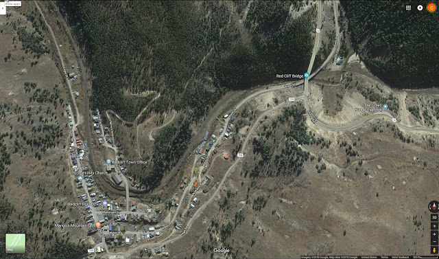
Redcliff now also shows the same sort of geometry, and can be at the other end of the layout where I need to turn the corner again. Much of the town is now in the foreground, but there are a few significant buildings that will be modeled in this arrangement.


The next view is around Silver Gulch, as the line emerges from the Eagle River Canyon. Notable here is that while the Eagle River is in the foreground, behind the track is a small pond whihc now can easily be modeled.


The next two images are of the Camp Hale area. Highway 24 will come from the background, cross over the railroad on an overpass, and the remains of Camp Hale become a foreground scene.


East of Camp Hale, we encounter Yoder Gulch, and the railroad climbs onto the hillside. Again, the perspective works very well.


As the railroad continues east, it clings to the hillside and passes through Dean Tunnel at Pando. Again, Highway 24 is in the foreground, so the perspective of the railfan is preserved. 


Between Pando and the next major element is Bennet Gulch, which is just a more nondescript area where the highway and the railroad close the elevation difference.


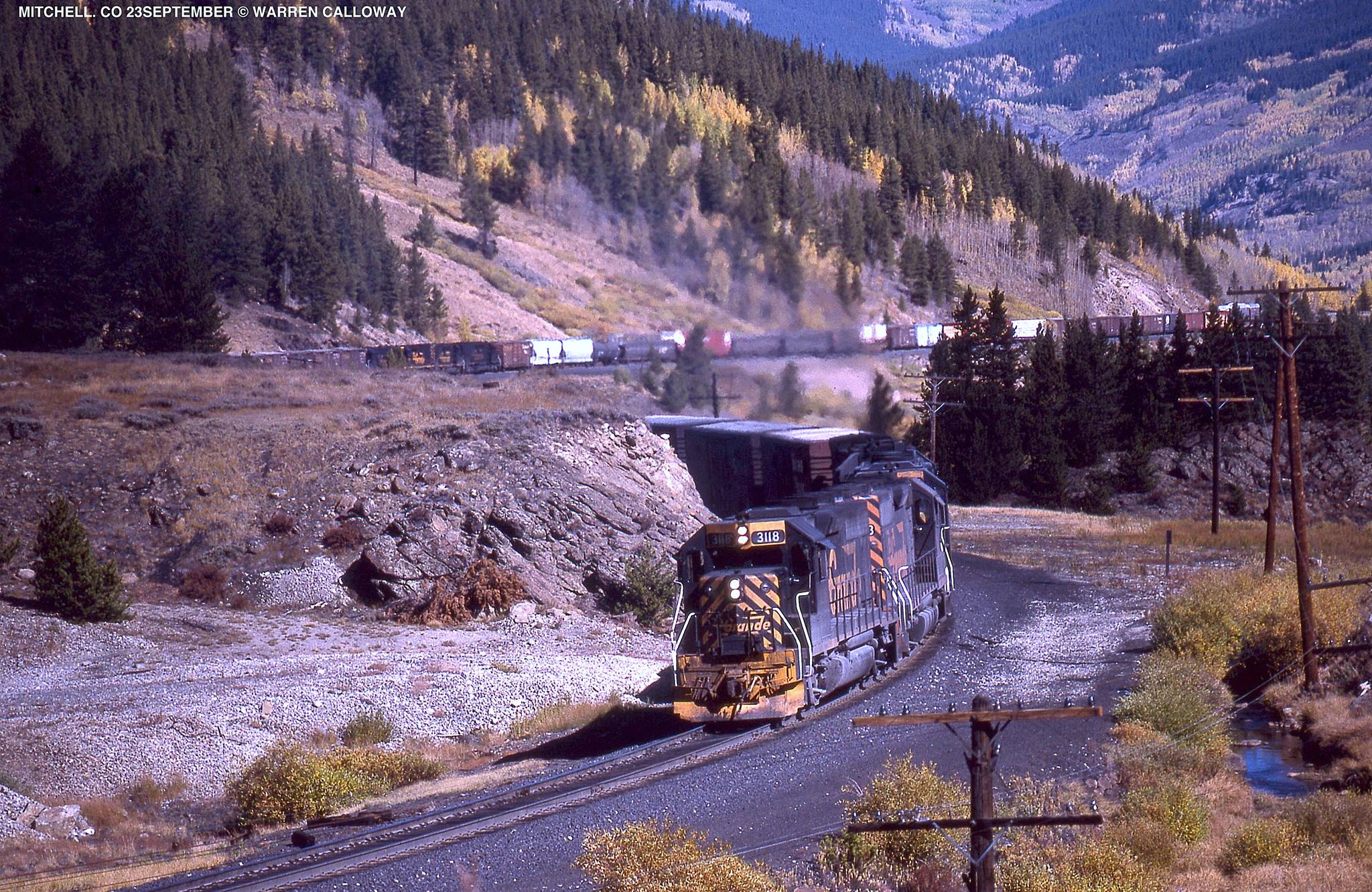
We finally arrive now at Mitchell, where the railroad makes a series of sweeping curves across the valley to gain elevation. This element is now true to the classic railfan view.


There is not a lot left to see before we reach the summit. After Mitchell, the line and the highway climb with the valley between them. The key feature here is that the valley rapidly narrows as we approach the tunnel.


The western portal of Tennessee Pass is at the end of the valley. on a sweeping curve that would lead into another end of the layout. 


I plan to model the highway climbing over the pass, while the railroad goes underneath, so this switchback will fit into the end of the layout and with a little more bending, will bring the viewer to the other side.


On the eastern side of the pass, the East Portal of Tennessee Pass exits into the Tennessee Pass siding. This is the farthest east siding I think I will model because I want to model the helpers cutting off. One challenge that now comes to play is that the wye would exit onto the front of the layout, and the wye is on the west end of the siding. I may model it with the wye to the eastern end of the siding so as to help the transition of the mainline into the helix which will need to rotate in the opposite direction as to the direction of the climb. I did just this on the prior layout. I also took the wye, and used the tail track to connect to Leadville. While not quite correct, it allowed me to give the Leadville/Malta turn somewhere to go. It actually is closer to the configuration when there was a connection to Leadville west of Malta, but this is a minor compromise to move this connection from Malta to the siding at Tennessee Pass. The operational benefits are just too good. 

So, all in all, it looks like this configuration will work quite well. I've taken these captures and built a little guide file so that as I work on the different areas I have some references to study for the design of each scene. So, that is Google Maps as a tool to conceptualize the design of a layout area.

One of my other concerns from the previous plan was that the space was a little tight to make everything work. But I have been considering that issue as well. My next post will focus on the plan to resolve those issues, and will define the footprint of the layout plan. 

Update: Just to maintain a little continuity here, I am still working on the T Layout, the HOn2Z cars, and the FMC4200 Hopper prototypes. I haven't forgotten those projects, and will post updates periodically in between layout planning updates.


Friday, September 8, 2017

Growing Doubts


With Irma bearing down on Florida, I'll take just a moment to express my hopes and prayers for those in its path. Please be safe. Even here in upstate South Carolina, I got emails yesterday and more today about preparing for Irma. Four Hours inland and this morning's reports were that we may expect Category 1 winds and rain if Irma continues.

Irma would be my fourth hurricane. I weathered a small one in Hawaii once on vacation, saw one run up into the Austin area while in college, flew to a conference ahead of one in Washington DC, and now Irma. I cannot even remember the names of the others. But its approach has just confirmed my feeling of ominous clouds on the horizon.


More than a month has passed since I expressed some doubts about the Tennessee Pass Layout I have been planning. And in that month, the layout doubts have continued to grow.

I still worry about the problems of reinstalling some of the modules should a new home be necessary - particularly the helix. It is so massive as a module - driven largely by the minimum curve radius that I just don't know if it would work. Oh, I am sure I can build it - and I can move it out - but could I ever move it in again. And if not, what is the point of moving it out, and without it, should I bother with making the rest movable.

But also in that time we have gained a new resident in the garage. My wife's sailing boat. It is beautiful, but the trailer is well, larger than I expected. It doesn't just take up a car space in the garage - but more like two. And so now when I look at the garage, I just don't see a future layout space, and so it looks like that expansion dream is pretty dead.

Worse yet, as we continue to settle into the home, I look at the remaining train space, and lament the closets along the one wall. Without them, the space is about 11 feet wide, minus a necessary aisle - so about 8 feet wide. With them, the space drops to just over 8 feet wide, but now requires two aisles. I had cheated and squeezed the Tennessee Pass Layout into this space, justifying a pair of narrow (e.g. 24 inch) aisles at each end. However, as the settling in process continues, it is becoming increasingly apparent that the closets will not be going in all likelihood, and that in fact, they will be needed to store some of my wife's collections. And if that is the case, a 24 inch aisle is not going to be acceptable. So, the space now drops to a width of maybe 2-3 feet.

Well, at that width, my 18" desired radius for standard gauge is pretty well out the door. I'd already compromised that down to 16-5/8" for the Tennessee Pass plan, but only in the helix and going downhill. Now, I'd have to be more drastic.

So, what are the options:

  • Explore the implications of a 15" minimum radius for Standard Gauge.
  • Consider Nn3 options instead.
  • There is z scale as an option.
  • Move to new concepts.
  • Wait for new space to emerge.

So, at the moment, the Tennessee Pass plan is on the shelf. I'll have to look at tighter radii, going to an Nn3 focus, or maybe jumping to Z. Or even finding another option - or hobby - or simply remaining an armchair modeler. Maybe when the storm passes, some new ideas will emerge.


Monday, July 31, 2017

Filling in the Details - Deck 2

Well, it has been a month since the last post, so I am well overdue for another. Since last time, I have been slowly filling in details to the Tennessee Pass Plan. But also having some doubts. More on those later.

Below is the current Deck 2 Plan. Let's look at it in detail:

Click to see full sized graphic
Since the last version, I have worked in the roads and bridges. The line emerges from staging (on loop 4 of the helix) and crosses over the Gore River on a deck girder bridge, before ducking under I-70. I-70 is arranged so that mirrors reflect both ends of the highway, and the combination of the highway and curving around the hillside with a backdrop on the front as well as the back, prevents anyone from actually seeing the train come out of the helix. The line curves around the left end of the layout crosses a county road at grade and swings into Minturn.

I completely reworked the west end of the Minturn yard to make it more functional, but also included the Minturn station, used for MOW storage, and both the Crew Hotel and Turntable Restaurant. Each should be close to scale size, as I took the measurements from an aerial photograph. I have also included a lumber yard and a warehouse at this end of the yard. I continued to allow for the possibility of modeling the wye - which I probably would not put in place in this location (too constricting) but if the layout were to be shown, a separate module could hold the tail track.

The East end of Minturn yard was also reworked a bit. I moved the engine house to the right, reworked the work and snow train tracks, and added a RIP track. There is now a dedicated fuel track, and I think the area flows much better. I also added a concrete plant and a spur which will host two as yet undetermined industries. This actually gives me a fair amount of switching for the Minturn Yard job (~8 spots), in addition to making up a couple of locals, and adding/servicing helper engines. Leaving Minturn, the railroad crosses Ballpark Road and Cemetery Road at grade, so there will also be a park with a baseball diamond (or at least part of one) and a small cemetery.

Rounding the right corner, I added in another stretch of the Eagle River, before the line crosses under US-24. US-24 actually climbs a steep switchback on its way to the town of Gilman (located above Belden. Meanwhile the tracks enter the Eagle River Canyon, crossing another deck girder bridge at Rex, before entering the Rock Creek Tunnel. Exiting the tunnel, I decided to freelance a pair of through truss bridges due to the geometry of the crossing of the Eagle River. The line curves to the left as the canyon narrows, and disappears from sight. Once again, the rock walls and backdrop restrict vision of this part of the canyon and hide the opening to the 8th lap of the helix. The bridges should help draw the viewer's eyes back tot he foreground, but another mirror will suggest that the canyon continues around the curve. There is still some topography to do on this level, but detailing the design has moved to Deck 3. So far, everything in the plan still works and works well.

I'd love to say that this sign is true, but several factors have created a few doubts in my planning. First, my space may not be what I once thought it would be. The garage part of the layout space is looking like it will be more difficult or further off from being available. However, the layout also may not be crewable either. This layout would probably need a Dispatcher, a Minturn Yardmaster, a Staging Hostler, and 3-4 road crews, including a helper crew. That is probably the crew capacity. Even with single person road crews, that is 6-7 people, and I am not sure where to find the operators. And if I did - would this make things congested? The Minturn Yard job would operate on the bottom side of the layout, and the Staging Hostler on the top side. The Dispatcher would be elsewhere. That puts the four road crews at various points around the layout - and conceivably, in the event of a meet, 3 road crews plus another job (Minturn or Staging) all on one side of the layout at the same time. Four bodies and some tighter than I would like aisles. I could operate with fewer folks, even just by myself, but part of the "fun" would be orchestrating the meets and passes on the hill.

So, if a less dispatcher intense operating layout more the preference? With that in mind, I have been thinking more about some alternatives, including a Salida based layout featuring the Monarch branch, or a protofreelanced version strongly based on that type of operation. That would give me the ability to consider other options for operations, but still allow me to test out some of the design/construction principles I have in mind. This alternate idea could also resolve the next doubt.

Another concern is the width of the modules. I originally set the maximum width at 42", knowing that I have a 44" wide sliding door that I can carry those through. What I did not think about was whether I would have a 44" door to carry them back into at the other end of the move. Unfortunately, with the layout running from 30" to 90", I can't even turn them on their sides to get through a narrower door - say 36". And unfortunately, the Helix is a 42" wide module without much hope for width reduction. So, I have been trying to think about whether or not I could make the wider modules split vertically, at least if needed to go through a 36" door. I do not yet have a good solution - but I am looking for one. The helix is the chief issue.

So, these are legitimate concerns. And I think that they will ultimately require some other plans to determine how best to proceed. But these doubts have been nagging, and have at least pulled some of my attention away from the plan. In addition, I've been putting time into my shapeways projects. I've gotten a number of designs back on line and available after the repricing for many shapeways materials, plus I have been working on plans for a T gauge layout for the Central Railroad Club (which I joined earlier in the year). I have to admit, I've had a recent spike in T gauge interest after seeing a new exhibition layout depicting the Firth of Forth Bridge in Edinburgh.


A link to the layout is shown below. More on these ideas next time.


All I can say is WOW! What a model in T! The real bridge is 8,094' long, which is 18 feet in T-scale. The layout is therefore on the order of 24' long. Quite the layout!


Thursday, June 29, 2017

A Design to Consider

Well, in my last post, I introduced a concept that I wanted to further refine. Primarily, I wanted to see if the idea would work as planned, i.e. that the grades and curves seemed to fit with the available space.

The plan still needs some work, but I have enough done that it is worth introducing. I selected the Tennessee Pass line from Minturn (on the western side of the continental divide) to Tennessee Pass Siding (located on the eastern part of the divide). This line has 3% grades in parts, and would certainly offer the opportunity to run long trains with helpers, but only limited switching. But the layout would let me experiment with train lengths, helper operations, and some multi-deck benchwork ideas that I have been developing. I'm including the route profile below:

The grade of interest is on the right side of the main diagram. Minturn is the helper base, and helpers are generally cut off on the other side of the summit at Tennessee Pass, Malta or Kobe. In this case, I would cut off helpers at Tennessee Pass, immediately before the helix down. So, with no further ado, let me introduce the layout.


Before showing the track plans of the various levels, let me show a few side views of the layout to help show the concept.

Minturn Side of the Layout

Tennessee Pass Siding Side of the Layout

So, these two views show the 3D render of the layout. The layout starts in staging (bottom image) and a train would run to the right and enter the helix. The train would climb the helix either to Minturn or Tennessee Pass Siding. If the train is headed for Minturn, the train would exit the helix on the left side of the upper image and run left to right through Minturn before wrapping around the end and entering the Rock Creek Tunnel area of the lower image. Again, the train runs left to right, and re-enters the helix for a couple of laps, before emerging at the Belden level of te upper image. Again, Left to right, entering the lower layout at the Pando level. Left to right again, returning around the end to the Pando Tunnel level of the layout on the upper image. Again left to right and the train enters the Tennessee Pass Tunnel at the right side of the upper picture. The train emerges out of the left side of the lower image, runs through Tennessee Pass Siding and then ducks back into the helix, heading down to staging. There is a small staging yard located off of Tennessee Pass siding that will represent Malta and Leadville.

Trains would climb from 34" in height in Staging to 80.5" at Tennessee Pass Siding. Yet the grades work, and the clearances are generally 8-12" plus. The 8" clearance is at the Tennessee Pass siding area and this could be fixed by raising the top of the layout if necessary - but I think at this elevation - 8" may be enough to work. It is even possible to build a raised platform of 8" or even 16" on the Tennessee Pass Siding side of the layout. That would make staging only 18" off the raised floor, but Rock Creek Tunnel would be about 35" off the raised floor. That is a little low, but Pando becomes 52" off the raised floor and Tennessee Pass Siding is at 64.5". Maybe a 14" or 15" elevated floor would be better - but both at acceptable.

Track Plan
There is a lot of detailing still to incorporate into the plan, but the concept works. I'll do some more analysis on the plan and discuss it in a future post. Until then, if tere is feedback, please share.

Friday, June 16, 2017

Considering a Concept

Well, with all the other items discussed, I have been doodling in the background. Having the train space in CAD is nice, as it allows a number of quick visualizations. One of the first drawings that I looked at is below.

Usable Space
Each of these lines represents the remaining space given aisles of various widths. Clearly, as long as the closets and sink (top of the picture) are in place, I am fairly limited. Access along the right side is a necessity, and the left side must deal with the door to the garage. About the only useable wall space at the moment is in the upper left hand corner - if the door to the garage does not have to open all the way - which it does not.


So, this is part of the fun. It is a challenge. Well, I have been following the Canadian Canyons Series on MR Video Plus. This is the most excited I have been about a project layout in Model Railroader in decades. I really like how the layout uses a helix to connect to a staging yard to form the loop. And so a concept may be born.

Looking at my space, and sketching out where the benchwork could go, I arrived at the following conceptual benchwork configuration.

Conceptual Benchwork
There is room for a helix on the left, and the trains could run around the layout and be followed by a crew all the way around the room. In only a few spots, do we have some sub-24" pinch points, and often we are wider. As a test layout, this concept has potential. It has the shelf style I am anticipating, yet could easily support full length trains. A cleaner benchwork drawing without the aisle potentials is shown below.

Dimensioned Benchwork
The layout is broken into 7 sections - each of which will fit out of the sliding door in the basement. Six sections are sceniced - and the seventh would be the helix. The layout may even be somewhat portable in case I need to move, or want to take it to a show.

So, this benchwork was not created solely by the space, but with a concept in mind. That concept is drawn from the Canadian Canyons Layout. I've drawn up a rough plan of the Canadian Canyons Layout on my own.


So, the tracks run through staging, climb the helix on the upper left hand side and then run through the sceniced layout, before descending the helix and returning to staging. It is a giant loop, but it sparked an idea. What if, my layout did much the same thing, climbed out of staging, ran around the perimeter of the layout and the returned to staging by descending the helix. A little quick math suggested that my visible run could be about 52 feet. In N-scale, that is about 1.6 miles. Since many of the places I am interested in modeling are centered around a grade, so, what I used that stretch to model the grade. Running a few quick calculations led to the following:

...a 1% grade would climb about 6.3 inches.
...a 2% grade would climb about 12.6 inches (think Moffat Line/Craig Branch).
...a 2.2% grade would climb about 13.9 inches (think Soldier Summit).
...a 3% grade would climb about 18.9 inches (think Tennessee Pass).

These are very interesting numbers. Playing with a bookshelf, I am convinced that in N scale, you need to have about 10 inches between the scenery base on the lower deck, and the underside of the upper deck. If you can get 12 inches, all the better, and then you need 2-4 inches for the deck structure. In other words, 12-16 inches of deck separation works for me - particularly if you are talking about 10-16 inch deep scenes. With this in mind, you could almost circle the available benchwork and climb to the next deck in the process.

So, what if the layout climbed out of the helix from staging, climbed around deck 1 to deck 2, circled around while still climbing on deck 2, and then descended the helix. Heck, you might be able to do it 3 or even 4 times. Interesting!

So, I have a concept for a layout that would start in staging, climb out of staging to a first deck, and then tackle a grade to the summit, before descending the helix back to staging. I've had similar ideas in the past and so I adopted a term for it - the double helix layout. This could be a chance to try it out.

Following some quick math, the footprint of the layout is 78.36 square feet, and I think I can more or less have staging + 3 decks, so a total of 313.5 square feet of layout, with a visible main line run of about 156 feet or almost 5 scale miles. Granted, the helix connecting the visible top with the staging level would be massive - but that too could be used for elephant staging (trains nose to tail) so you would not "see" the delay climbing the helix, and going down the helix could be automated or managed by the staging hostler. But a 5 scale mile helper grade, that could be a site to be seen.

Okay, so back to the concepts - Focusing on standard gauge for a minute - the Moffat would be the toughest, the grade is at the low end, which would lead to minimal clearances throughout, and if you had some flatter spots at towns, the climb distance it not there. Furthermore, some of the signature features, such as the Big 10 curves, don't work well at all. The Craig Branch has similar issues with some of the scenes (Crater loops), but perhaps a piece of it could be achieved. Soldier Summit does a bit better, it is worth considering, and given that there are few real towns on the eastern side - maybe. The western side has Gilluly Loops - that won't fit well at all. That leads us to Tennessee Pass, with a western side with 3% grades, virtually all a helper district, only a few sidings, and even where it levels out, we are often still talking about 1-2% grades. Promising.

So, it sounds like I have some concepts to draw up, and let us see how they look. Then there are some other options if I look at the Narrow Gauge options too. But I'm going to start with the standard gauge ideas and see how they look.


Monday, January 30, 2017

Ghosts of Tennessee Pass

I didn't really start railfanning until the early 1990s. One of my first spots I visited was Tennessee Pass. And it was a good thing I did, because only a few years later Tennessee Pass fell silent. I regret that I only visited about 3 or 4 times, but most of those times were full of action. I had been fortunate to see the pass earlier in my childhood with my father, and even eat in the Turntable Cafe in Minturn. I do remember seeing the helpers in the yard, and the trains leaving for the pass, but I honestly didn't realize how rare what I was seeing would become.


So, I've seen the pass go from solid Rio Grande, to Rio Grande/Southern Pacific to Southern Pacific/Union Pacific and to silence.

The western side of the pass begins at Minturn. Minturn is a helper town just west of Vail. Vail is now rapidly growing into Minturn. To the west, is the Eagle River valley, and a number of local industries that would be nice to include in any model. These towns run all the way to Dotsero, where the Moffat line joins up.

East of Minturn, the line begins a climb with grades of up to 3%! Trains with 8, 10, 12 or even more units climbed this grade. No wonder that UP retired the line. The initial part of the line slips through a canyon, past the now abandoned New Jersey Zinc Mine (and Superfund site) located with Belden siding, and the little town of Red Cliff, before climbing out of the canyon at Pando. At Pando, we have another passing track, and then Dean or Pando Tunnel. Finally, the train makes its last assault on the pass with the Mitchell Curves before reaching the summit tunnel.

Helpers usually ran on through the tunnel and were cut off at Tennessee Pass siding, or Malta siding on the other side of the pass. They might run back light, or swing onto another train struggling to surmount the 10,000 foot pass. Malta siding is also the connection to Leadville, or at least it was, along with a connection to an isolated piece of Colorado and Southern trackage (operated by the Burlington Northern) that ran up to the Climax mine, high on Fremont Pass. 

Continuing East from Malta, the line follows the Arkansas River, through towns such as Buena Vista, Nathrop and Salida. The line passes through the scenic Brown Canyon, past a beautiful bridge near Princeton siding (which begs to be modeled) and along the Collegiate Peaks of Colorado. Salida was once a division point, and was where the Standard Gauge and the Narrow Gauge met. IT was out of Salida that the Narrow Gauge 3rd Division left for Utah. But alas, the Narrow Gauge was removed, although the Monarch Branch was standard gauged and ran into the 1980s. This branch was unique on the Rio Grande, with a pair of switchbacks. Its operation is fascinating, and the subject of more than one book and video. Clearly, railfans loved the line.

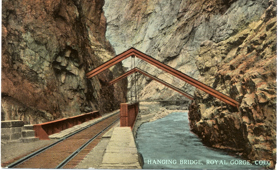
East of Salida, the railroad works through another canyon, passes sidings such as Spikebuck, Texas Creek, and Parkdale, before plunging through the Royal Gorge. Within the Gorge, you have the hanging bridge, but otherwise, scenes only scene by the white water rafters, or riders of the railroad.

The railroad emerges in Canon City. The stretch from Canon City to Pueblo is itself interesting. The Santa Fe had some access along this stretch to provide service to customers. There are switching opportunities in Canon City, Florence, and Portland. Portland hosts a major cement industry. In addition, there is an Gypsum Wallboard plant along the line. Before entering Pueblo, the line transverses some interesting and unique scenery as the climate becomes much more of a dry high plains topography. 

Pueblo itself is a major endeavor, with local industries, multiple rail yards, junctions between the Joint Line to Denver, the line south to Walsenburg and La Veta Pass, as well as Trinidad and Raton Pass. East, the Rio Grande operated the MP line to Kansas and ultimately to Saint Louis. The Santa Fe, Missouri Pacific and Burlington Northern both came into Pueblo. There is even a fantastic, iconic passenger station. Also of interest, just south or Pueblo is the Minnequa (Colorado Fuel and Iron) Steel Mill, which even boasted a narrow gauge plant railway at one point. There are several power plants nearby, and north of Pueblo is Fort Carson if you like military trains.

All in all, the subdivision runs about 230 miles. It is a lot of railroad. The grades on the eastern side are much less than those on the western side, but are still significant. So, massive freight trains, even inter-modal trains plied the line. Double stacks, while rare could transverse the line since the tunnels were not as restrictive as those on the Moffat line. However, passenger service (even Amtrak) has been non-existent since the 1960s. So, the line is interesting and historically relevant. A fantastic model of the line has been built by Rob Carey (in N-scale). The line was also featured in Model Railroad Hobbyist Magazine and N Scale Railroading's May/June 2009 Issue.


I've never seen this layout in person. But it certainly is fascinating.

So, as I have done before, lets talk Operational LDEs:

  • Eagle River Valley Industries (W);
  • Minturn (W);
  • New Jersey Zinc Mine (W);
  • Belden siding (W);
  • Pando siding (W);
  • Malta siding (E);
  • Leadville Branch (E);
  • Salida (E);
  • Monarch Branch (E);
  • Parkdale siding and quarry (E);
  • Hanging Bridge (E);
  • Canon City/Florence (E);
  • Portland (E);
  • Pueblo Yard/Industries (E);
  • Pueblo Union Station (E); 
  • Junctions to other lines (E); and
  • Minnequa Steel Branch (E).

The Scenic LDEs include:

  • Eagle River Canyon (W);
  • Red Cliff (W);
  • Camp Hale (W);
  • Dean Tunnel (W);
  • Mitchell Curves (W);
  • Tennessee Pass Tunnel (W);
  • Mirror Lakes (E);
  • Princeton Bridge (E);
  • Buena Vista/Nathrop (E);
  • Brown Canon (E);
  • Salida Canon (E);
  • Royal Gorge (E);
  • Swallows siding (E); and
  • Goodnight (End of Double Track of of Pueblo) (E).

That is 17 operational LDEs, and 14 scenic LDEs that I would prioritize in the layout. 5 of the operational LDEs and 6 of the scenic LDEs are on the west side. Clearly, the eastern side of this line is much more demanding than the western side. But of course, that also depends on the fidelity of the layout plan too. Extending the western side to include Malta and Leadville adds 2 more operational LDEs, and maybe 1 scenic LDE, so you could quite conceivably model the west side in a reasonable area. Extending to Salida, adds 2 more operational LDEs and 3-4 scenic LDEs. Again not unreasonable. But there is a lot of "good stuff" near Pueblo operationally, even if the scenery is less compelling (6 operational LDEs and 2 scenic LDEs between Pueblo and Canon City).