


One of the comments on this plan resonated greatly with me, as I had adopted a particular perspective on the layout based on the view from Highway 24 in Minturn. Unfortunately, this view puts several of the later scenes in perspectives that are not those typically seen by railfans, and that always bothered me. The suggestion was simply to flip the view in Minturn to look at the yard with the town in the background rather than the foreground.
As part of the planning for this effort, I went back to Google Maps and captured a set of images of the relevant areas oriented in the viewing perspective. So, here is the view at Minturn.

So, in this configuration an eastbound train moves from right to left through the scene. There are obviously a few nice advantages already apparent. The wye would extend into the backdrop, the town would be in the background and on the backdrop rather than lost off of the front of the layout.

Further to the east (geographic south) of Minturn, we reach the point where Highway 24 will cross over the railroad and will climb off the front of the layout.


Continuing eastward, we quickly arrive at the area around Belden. Here, we see a very different perspective than what I have normally scene modeled. The mine here is now in the foreground, and the tunnels are in the back of the scene. Most models I have scene have the mine in the background. However, here we get a really nice effect, as the mine is located in a turnback curve that will look right at the end of the layout. Previously, I had to soften this curve, and sacrifice much of the bend to maintain the geometry of the layout. Further, the mine will now be closer to the front, so the NJ Zinc Mine will need to be modeled with increased fidelity compared to a model in the background.
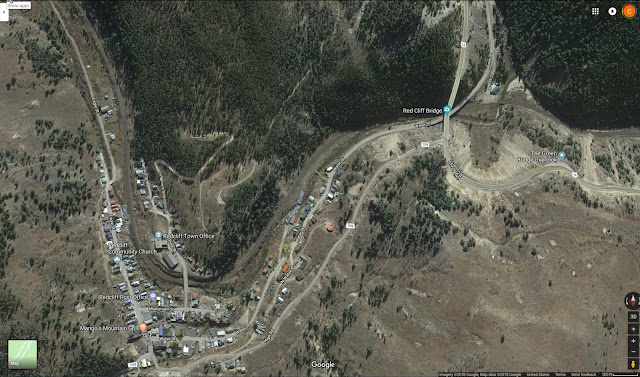
Redcliff now also shows the same sort of geometry, and can be at the other end of the layout where I need to turn the corner again. Much of the town is now in the foreground, but there are a few significant buildings that will be modeled in this arrangement.

The next view is around Silver Gulch, as the line emerges from the Eagle River Canyon. Notable here is that while the Eagle River is in the foreground, behind the track is a small pond whihc now can easily be modeled.


The next two images are of the Camp Hale area. Highway 24 will come from the background, cross over the railroad on an overpass, and the remains of Camp Hale become a foreground scene.

East of Camp Hale, we encounter Yoder Gulch, and the railroad climbs onto the hillside. Again, the perspective works very well.


As the railroad continues east, it clings to the hillside and passes through Dean Tunnel at Pando. Again, Highway 24 is in the foreground, so the perspective of the railfan is preserved.

Between Pando and the next major element is Bennet Gulch, which is just a more nondescript area where the highway and the railroad close the elevation difference.

We finally arrive now at Mitchell, where the railroad makes a series of sweeping curves across the valley to gain elevation. This element is now true to the classic railfan view.

There is not a lot left to see before we reach the summit. After Mitchell, the line and the highway climb with the valley between them. The key feature here is that the valley rapidly narrows as we approach the tunnel.

The western portal of Tennessee Pass is at the end of the valley. on a sweeping curve that would lead into another end of the layout.

I plan to model the highway climbing over the pass, while the railroad goes underneath, so this switchback will fit into the end of the layout and with a little more bending, will bring the viewer to the other side.

On the eastern side of the pass, the East Portal of Tennessee Pass exits into the Tennessee Pass siding. This is the farthest east siding I think I will model because I want to model the helpers cutting off. One challenge that now comes to play is that the wye would exit onto the front of the layout, and the wye is on the west end of the siding. I may model it with the wye to the eastern end of the siding so as to help the transition of the mainline into the helix which will need to rotate in the opposite direction as to the direction of the climb. I did just this on the prior layout. I also took the wye, and used the tail track to connect to Leadville. While not quite correct, it allowed me to give the Leadville/Malta turn somewhere to go. It actually is closer to the configuration when there was a connection to Leadville west of Malta, but this is a minor compromise to move this connection from Malta to the siding at Tennessee Pass. The operational benefits are just too good.
So, all in all, it looks like this configuration will work quite well. I've taken these captures and built a little guide file so that as I work on the different areas I have some references to study for the design of each scene. So, that is Google Maps as a tool to conceptualize the design of a layout area.
One of my other concerns from the previous plan was that the space was a little tight to make everything work. But I have been considering that issue as well. My next post will focus on the plan to resolve those issues, and will define the footprint of the layout plan.
Update: Just to maintain a little continuity here, I am still working on the T Layout, the HOn2Z cars, and the FMC4200 Hopper prototypes. I haven't forgotten those projects, and will post updates periodically in between layout planning updates.
No comments:
Post a Comment